Method for manufacturing a cannula assembly

a manufacturing method and cannula technology, applied in the field of cannulas, can solve the problems of imposing further substantial limitations on the types of plastics, undesirable alteration of physical characteristics, strength, etc., and achieve the effects of reducing manufacturing costs, increasing capacity, and sufficient strength

Inactive Publication Date: 2006-04-11
FENWAL
View PDF56 Cites 14 Cited by
  • Summary
  • Abstract
  • Description
  • Claims
  • Application Information

AI Technical Summary

Benefits of technology

[0006]These and other problems are addressed by the method and device configurations of the present invention. Generally, the present invention includes a cannula assembly having an interference fit between the cannula and a surface of a hub member. The interference fit has sufficient strength that adhesives are not required to secure the cannula to the hub member. In some cases, the ability to manufacture a cannula assembly without using adhesives represents an approximate 50% reduction in manufacturing costs and a significantly increased capacity for a given plant size compared to conventional manufacturing processes.

Problems solved by technology

Third, the hub must hold onto the needle notwithstanding a film of lubricant such as silicone located on the needle.
First, there can be incompatability with the epoxies used to secure the cannula to the hub and the plastic material in the hub.
Second, the need to cure some adhesives using ultraviolet curing requires a hub that is substantially transparent.
This requirement imposes further substantial limitations on the types of plastics that can be used to form the hub.
The use of a thermal cure of the adhesive can cause physical or chemical changes of the plastic which can undesirably alter the physical characteristics (e.g., strength) of the material.
In addition, all the above processes require extra time in to manufacture a cannula assembly, which significantly increases costs.

Method used


Image

  • Method for manufacturing a cannula assembly
  • Method for manufacturing a cannula assembly
  • Method for manufacturing a cannula assembly

Examples


Embodiment Construction

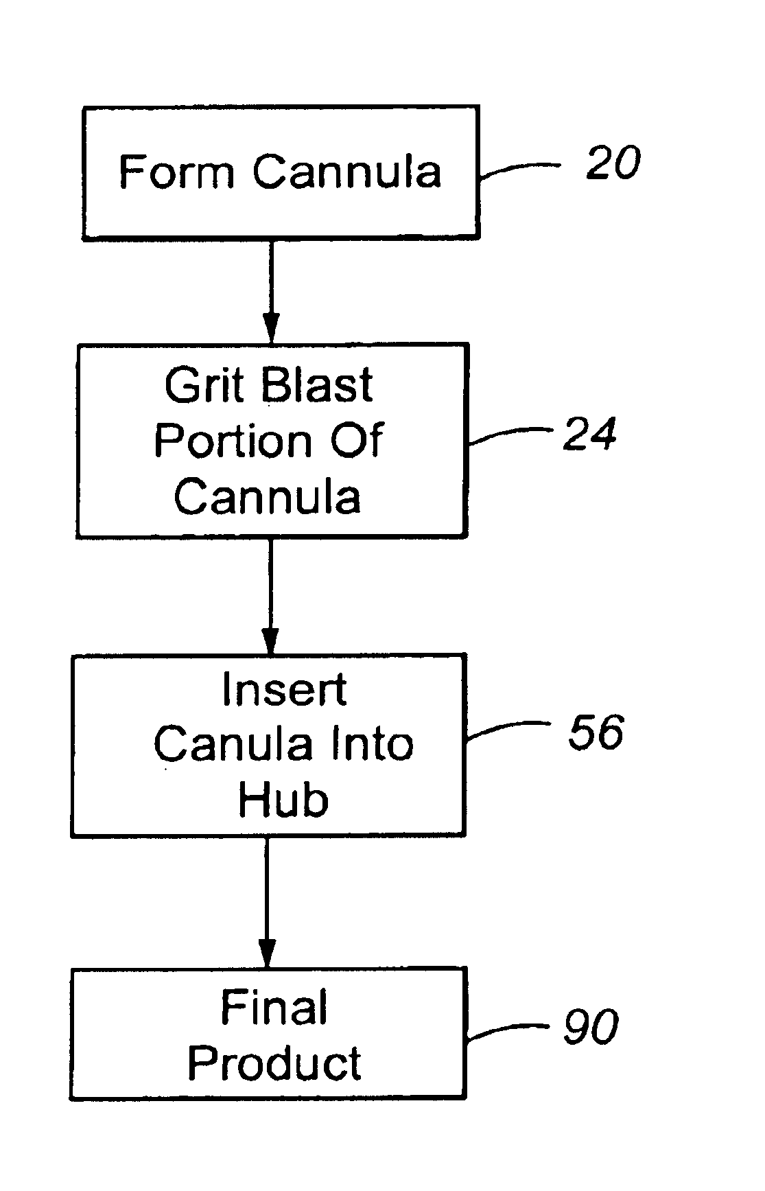
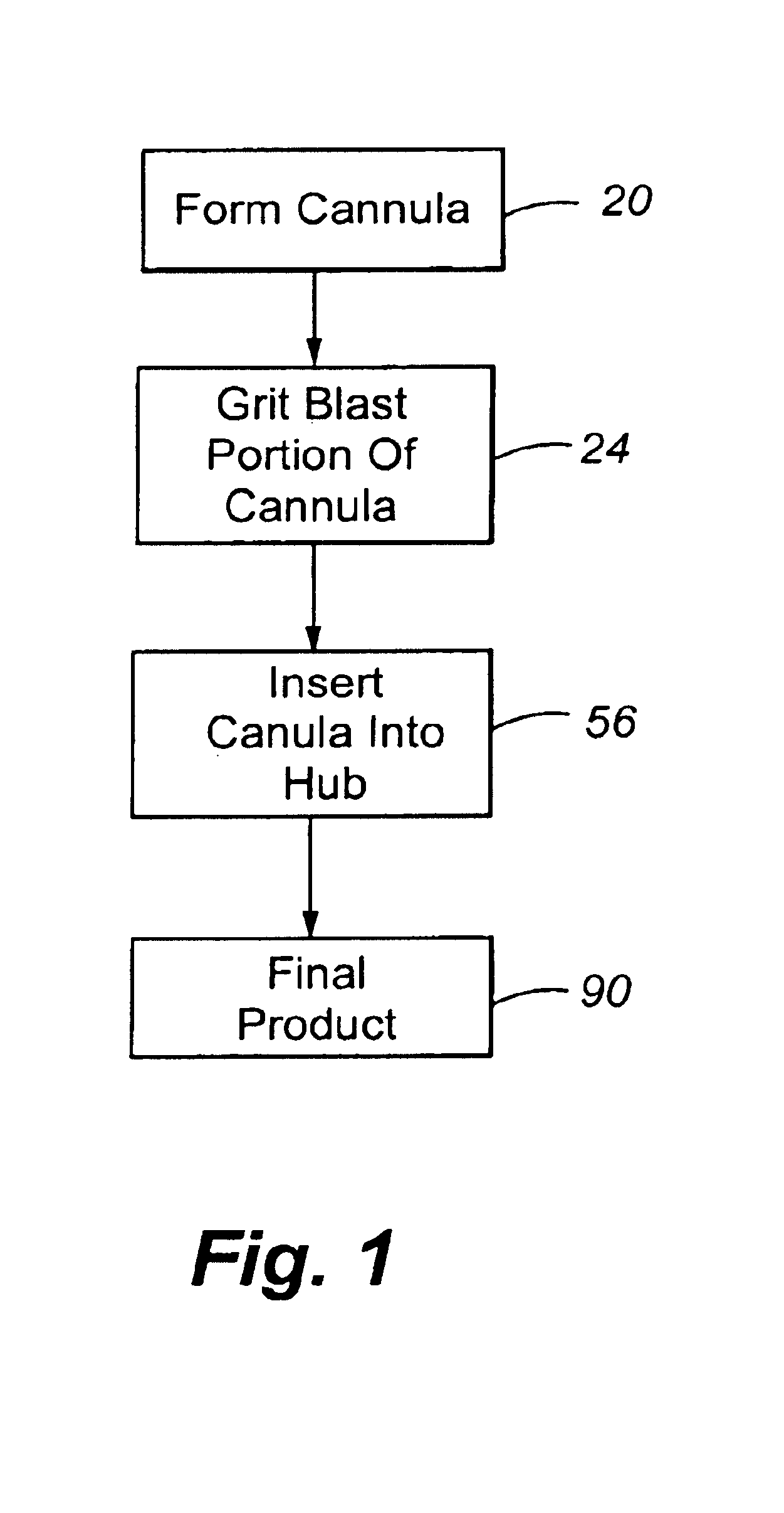
[0042]The manufacturing process of the present invention will be described with reference to FIG. 1. In the first step 20, the cannula is formed by a suitable process. Such processes are conventional. Typically, the cannula is formed from a high strength, nontoxic material such as stainless steel. The cannula can be of any length or diameter, depending upon the application.

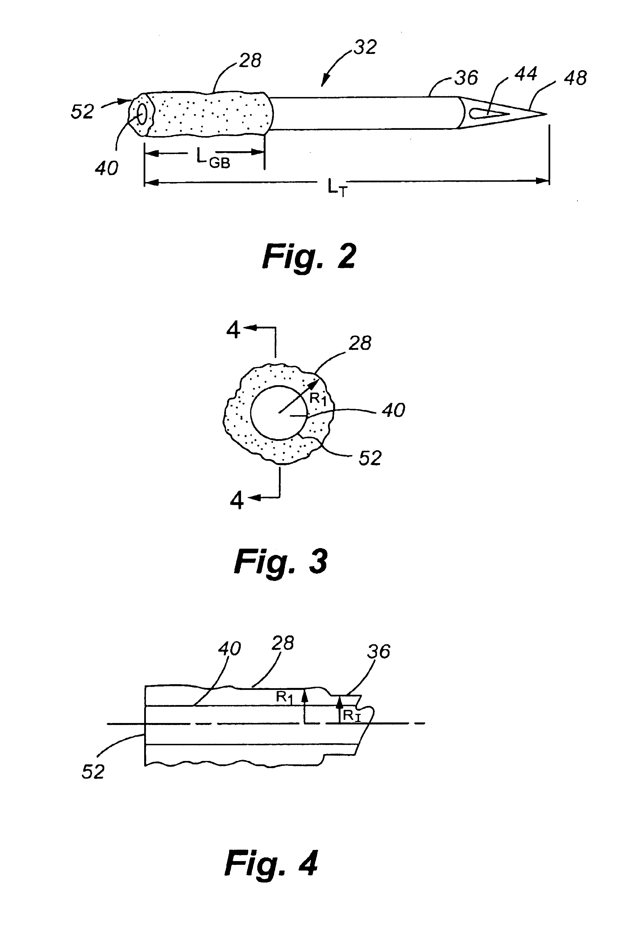
[0043]In the second step 24, the proximal (nonpuncturing or unpointed or blunt) end of the cannula is grit blasted to form a roughened surface or roughened portion of the cannula.

[0044]The depth of the grit blast is sufficiently high to permit a strong (nonadhesive) bond to form between the hub member and the cannula. Typically, the grit blast depth provides a radius for the roughened portion which creates an outer diameter greater than the inner diameter of the hub bore. However, the outer diameter of the roughened portion preferably is a diameter permissive for insertion into the hub bore (e.g., with an insertio...


PUM

PropertyMeasurementUnit
radiusaaaaaaaaaa
lengthaaaaaaaaaa
lengthaaaaaaaaaa

Abstract

The present invention is directed to a novel process for inserting a cannula, such as a hypodermic needle, into a hub member by roughening a first portion of the cannula while leaving a second portion substantially smooth such that the first portion forms an interference fit and the second portion a line-to-line fit with the hub bore. In the absence of an adhesive, the second portion is passed through the hub bore followed by the first portion. The first portion is forced into the hub bore to provide an adhesive-free interference fit that is capable of resisting puncturing forces during normal use.

Description

CROSS-REFERENCE TO RELATED APPLICATION[0001]The present application is a divisional of U.S. patent application Ser. No. 09 / 866,139, filed May 25, 2001 now U.S. Pat. No. 6,709,428, of the same title, which claims priority from U.S. Provisional Application, Ser. No. 60 / 207,709, filed May 26, 2000, each of which is incorporated herein by this reference.FIELD OF THE INVENTION[0002]The present application is directed generally to cannulas and specifically to the securement of the cannula to a hub member.BACKGROUND OF THE INVENTION[0003]To be acceptable, processes for manufacturing cannula assemblies, which include a hub and cannula, must satisfy several requirements. For example, the process must have a low incidence of damaging the point of the cannula. Second, the process must have a low incidence of plugging the hollow passageway extending the length of the cannula. Third, the hub must hold onto the needle notwithstanding a film of lubricant such as silicone located on the needle. As ...

Claims


Application Information

Patent Timeline
Patent Type & Authority Patents(United States)
IPC IPC(8): A61B17/34A61M5/32A61M5/158A61M5/34B21G1/08
CPCA61B17/3417A61M5/343B21G1/08B29C65/64Y10T29/53396A61M5/158B29K2021/00B29K2023/12B29K2025/00B29K2027/06B29K2069/00B29K2305/00B29K2305/12B29L2031/7548Y10T29/53339Y10T29/49945A61B2017/00526A61M5/346A61M2207/00B29C66/71B29C66/73161B29C66/74283B29K2025/06
Inventor SAGSTETTER, WILLIAM E.
Owner FENWAL
Why Eureka
Try Eureka