Centrifugal pellet dryer with plastic wall panels

a technology of plastic wall panels and centrifugal pellet dryers, which is applied in the direction of filtration separation, lighting and heating apparatus, separation processes, etc., can solve the problems of objectionable noise levels in the vicinity of the dryers, and achieve the effect of reducing noise levels and high noise levels

Inactive Publication Date: 2006-04-11
GALA INDUSTRIES INC
View PDF19 Cites 71 Cited by
  • Summary
  • Abstract
  • Description
  • Claims
  • Application Information

AI Technical Summary

Benefits of technology

[0010]The vertical side edges of the plastic wall panels are sealingly interconnected to provide a substantially rigid plastic wall assembly, and the top and bottom sections receive the top and bottom edges of the side walls around their periphery to form a watertight housing. It has been surprisingly found that such a plastic wall housing will substantially reduce outward transmission of noise produced by the movement of the wet pellets and components of the dryer and the impact of the wet pellets against the interior of the separating screen.
[0022]Still yet another object of this invention to be specifically enumerated herein is to provide a centrifugal pellet dryer in accordance with the preceding objects which will conform to conventional forms of manufacture, be of simple construction and easy to operate so as to provide a dryer that will be economically feasible, long lasting and relatively trouble free in operation.

Problems solved by technology

Operation of centrifugal pellet dryers of this type, however, produce noise levels that can be objectionable to personnel in the vicinity of the dryers.

Method used


Image

  • Centrifugal pellet dryer with plastic wall panels
  • Centrifugal pellet dryer with plastic wall panels
  • Centrifugal pellet dryer with plastic wall panels

Examples


Embodiment Construction

[0039]Although preferred embodiments of the invention are explained in detail, it is to be understood that other embodiments are possible. Accordingly, it is not intended that the invention is to be limited in its scope to the details of constructions and arrangement of components set forth in the following description or illustrated in the drawings. The invention is capable of other embodiments and of being practiced or carried out in various ways. Also, in describing the preferred embodiments, specific terminology will be resorted to for the sake of clarity. It is to be understood that each specific term includes all technical equivalents which operate in a similar manner to accomplish a similar purpose.

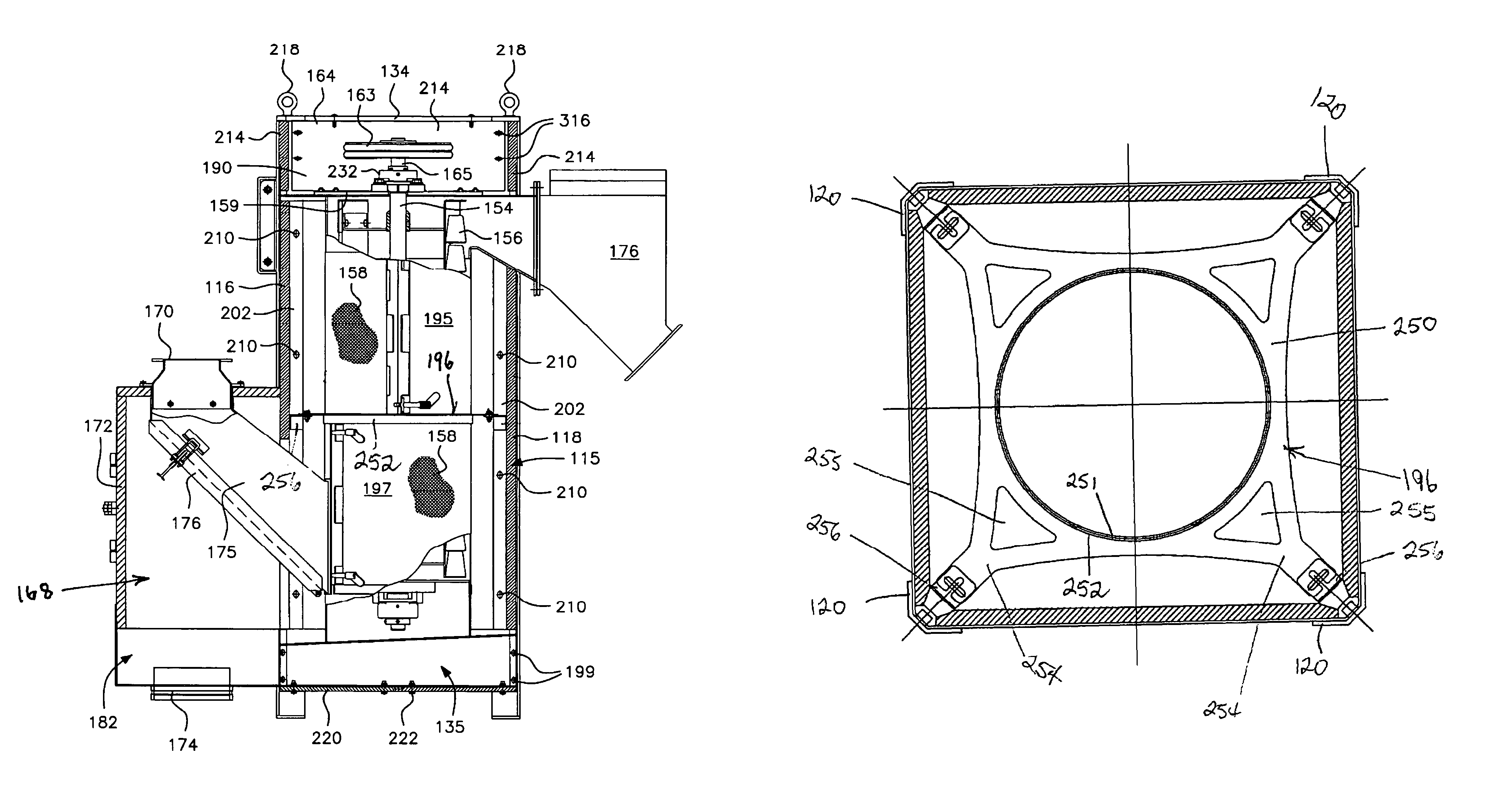
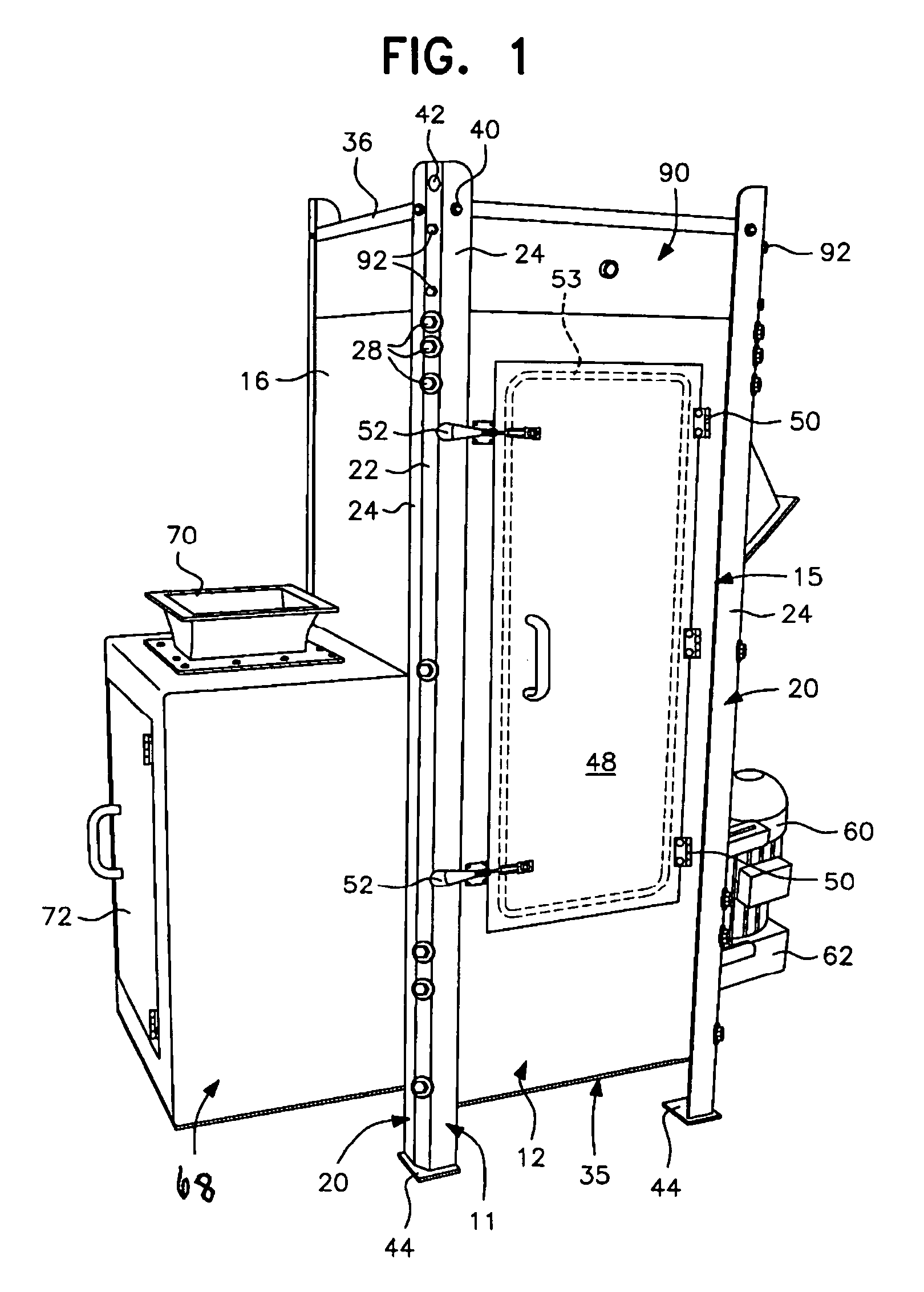
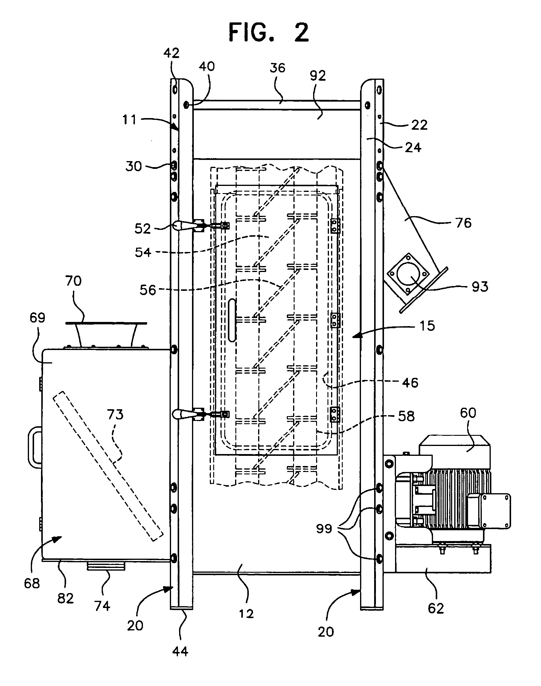
[0040]Referring to FIGS. 1–5 of the drawings, one centrifugal pellet dryer in accordance with the present invention is generally designated by reference numeral 10. The dryer 10 includes a substantially rigid metal support framework, generally designated by reference numeral 11, ha...


PUM

PropertyMeasurementUnit
thickaaaaaaaaaa
distanceaaaaaaaaaa
thickaaaaaaaaaa

Abstract

A centrifugal pellet dryer including a stationary cylindrical screen, a driven elevating rotor in said screen elevating wet pellets inside the screen and imparting radial forces to the wet pellets to impact them against the interior of the screen to enable moisture on the pellets to be separated and discharged through the screen, a housing enclosing the screen and rotor and including an inlet for a slurry of pellets, an outlet for dried pellets and an outlet for water removed from the pellets. The side walls of the housing are constructed of a plurality of relatively large, flat panels made of plastic sheet material are supported in a metal framework to attenuate noise of the dryer produced by rotation of the drier rotor and impact of the wet pellets against the screen. A dewaterer in advance of the dryer also has walls made of plastic sheet material.

Description

BACKGROUND OF THE INVENTION[0001]1. Field of the Invention[0002]The present invention generally relates to centrifugal pellet dryers of the type in which a driven rotor impacts wet pellets exiting an underwater pelletizer against the interior surface of a cylindrical screen which allows water to pass therethrough and the pellets to continue upwardly inside the screen to a discharge outlet. More specifically, the present invention is directed to such a centrifugal pellet dryer in which the housing walls are made of a plastic sheet material to attenuate the noise produced by the centrifugal dryer.[0003]2. Description of the Prior Art[0004]Centrifugal pellet dryers have been effectively used to separate water and moisture from pellets, such as those formed by an underwater pelletizer in which the pellets and water are discharged from the pelletizer cutting chamber as a water and pellet slurry. The water and pellet slurry exiting the pelletizer is typically fed first through a dewaterin...

Claims


Application Information

Patent Timeline
Patent Type & Authority Patents(United States)
IPC IPC(8): F26B17/24
CPCF26B17/24B29B9/16F26B25/12B29B9/065F26B5/08
Inventor MYNES, JEFFREY S.
Owner GALA INDUSTRIES INC
Why Eureka
Try Eureka