Drive apparatus

a technology of inducing apparatus and driving shaft, which is applied in the direction of electrical apparatus, dynamo-electric machines, bearings, etc., can solve the problems of limited life of elastomer and rubber element couplings, and high energy losses in the form of friction and heat loss

Inactive Publication Date: 2006-04-11
THE GABRIELLE BAKEY FAMILY TRUST
View PDF26 Cites 48 Cited by
  • Summary
  • Abstract
  • Description
  • Claims
  • Application Information

AI Technical Summary

Benefits of technology

[0004]One advantage of the present drive apparatus over those known in the art involving conventional mechanical couplings is that there are minimal frictional or heat losses because the or each secondary drive shaft is not in physical contact with the primary shaft. Further, a mechanical advantage can be created by positioning a number of secondary shafts in proximity to the primary shaft, so that one shaft induces rotation in a plurality of secondary shafts simultaneously.
[0011]Preferably the or each secondary shaft is fitted with an additional mass to increase its rotational inertia.
[0012]In this regard, in a third aspect the present invention provides apparatus for inducing drive including a primary drive shaft and one or more secondary drive shafts, the primary shaft and secondary shaft(s) each fitted with magnetic means oriented such that, when the primary shaft is rotated, the or each secondary shaft is caused to rotate due to attractive or repulsive magnetic forces, with the secondary shaft(s) each being fitted with an additional mass to increase its rotational inertia.
[0013]By increasing the rotational inertia of each secondary shaft, once it is caused to rotate by the primary shaft, its tendency is to continue to rotate. It has been observed that this enhances the performance of the apparatus and makes for a smoother induction of drive from the primary shaft to the secondary shaft(s).
[0029]An advantage of the fourth aspect of the present invention is that the motive mechanism can, for example, provide a drive for a fluid or can be driven by that fluid, with the primary and secondary shafts facilitating a coupling to the motive mechanism. Thus, a motor connected to one shaft can drive the motive mechanism connected to the other, or the motive mechanism can receive energy and transfer it to its shaft, and that energy can then be transferred via the magnetic coupling to a generator coupled to the other shaft. The fluid can conveniently be flowing through a sealed housing such as a pipe, and thus the drive can provide a very effective and completely sealed means of transferring energy to / from a fluid.

Problems solved by technology

There are many problems associated with mechanical couplings, such as the requirement for periodic lubrication of gears, close alignment requirements of disc, diaphragm and hydraulic couplings and the limited life of elastomer and rubber element couplings.
Energy losses in the form of friction and heat loss can be considerable in such apparatus.

Method used


Image

  • Drive apparatus
  • Drive apparatus
  • Drive apparatus

Examples


Embodiment Construction

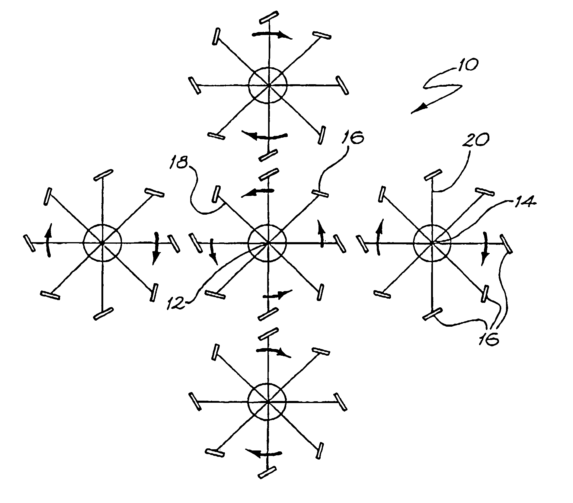
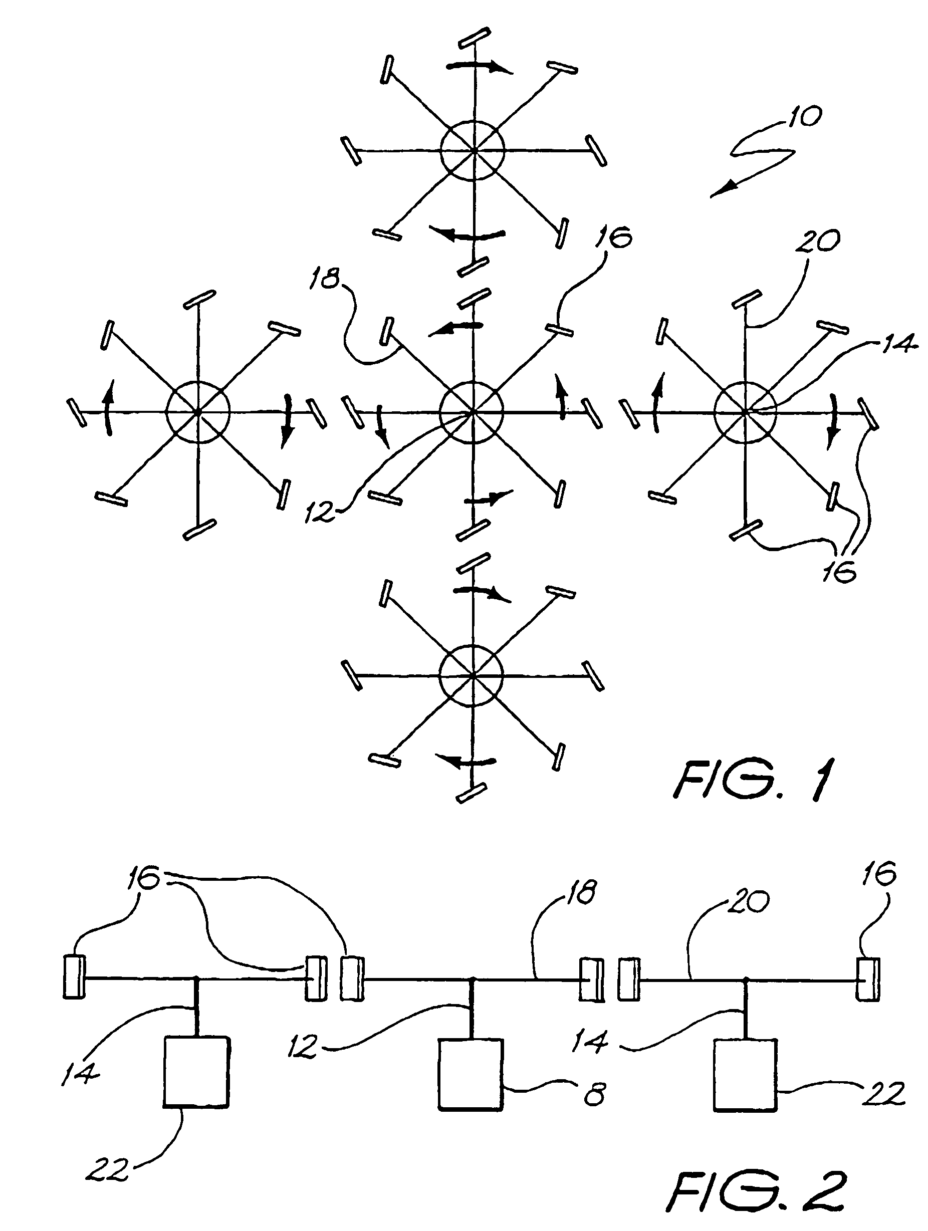
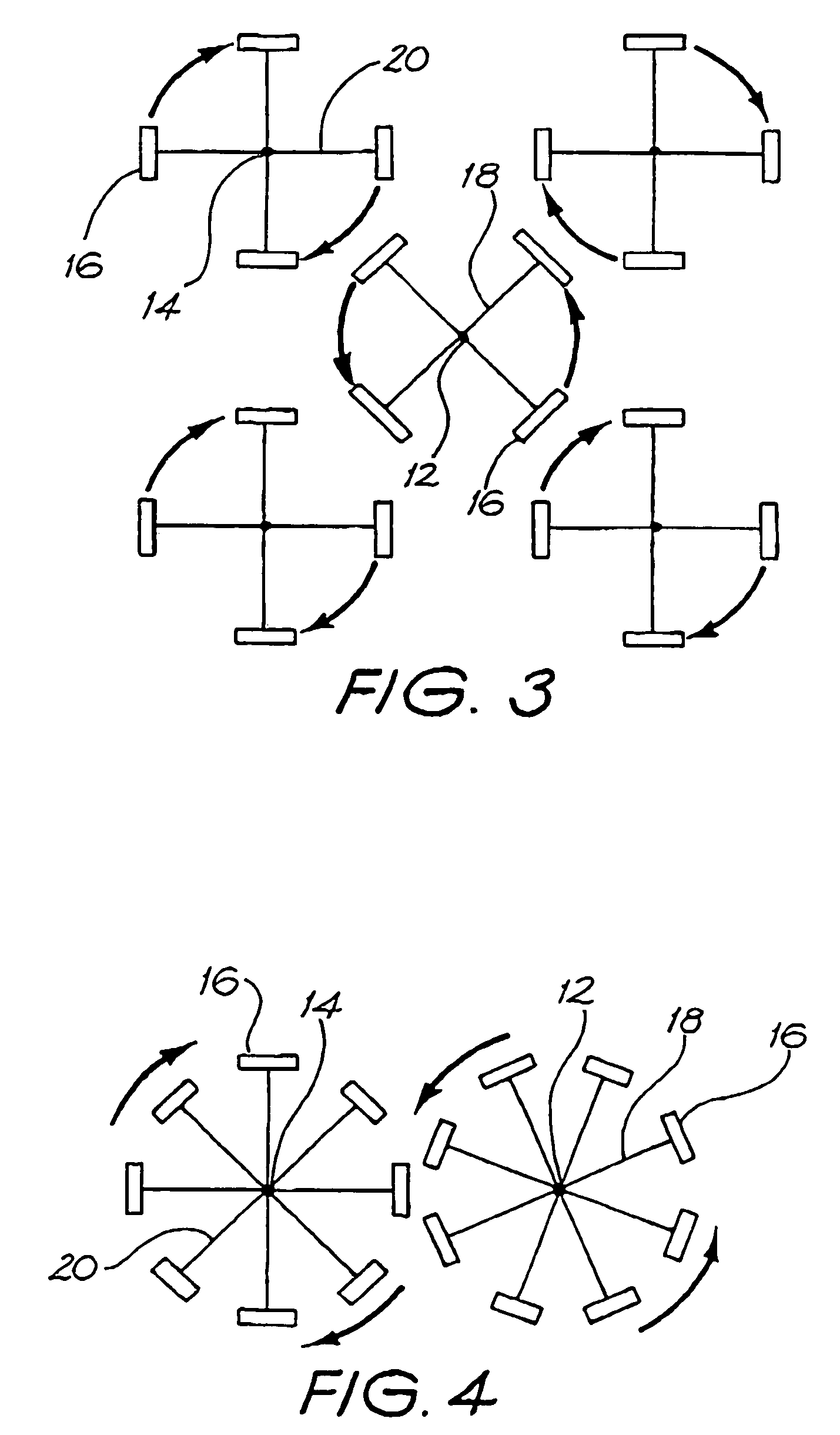
[0066]Referring to the drawings, apparatus for inducing drive 10 is shown in FIG. 1 and includes a primary drive shaft 12 and four secondary drive shafts 14 spaced evenly around shaft 12. The primary shaft 12 and secondary shafts 14 are each fitted with magnetic means, typically in the form of permanent magnets 16 which are oriented such that when the primary shaft 12 is rotated the secondary shafts 14 are caused to rotate due to either attractive or repulsive magnetic forces (either directional force works). The primary shaft 12 is connected to and rotated by a rotational energy source such as a motor 8 powered by electricity or a battery, although any source of energy to cause rotation of the primary shaft is within the scope of the invention, for example rotation by connection to a water wheel, windmill, wave energy source, solar energy source, etc.

[0067]The magnetic means can also comprise an electromagnet or any other magnetisable material, for example metals such as iron, form...


PUM


Abstract

An apparatus for inducing drive is shown that includes a primary drive shaft and four secondary drive shafts. The primary shaft and secondary shafts are fitted with magnets that are oriented such that when the primary shaft is rotated the secondary shafts are caused to rotate due to attractive or repulsive forces. The primary shaft is connected to and rotated by a rotational energy source such as a motor powered by electricity or a battery, although any source of energy to cause rotation of the primary shaft may be used. Each secondary shaft is fitted with two annular magnetic discs that are oriented to vertically support the weight of the shaft (and any attachments / fittings thereto) above the alternating or generating device. The discs can be arranged to provide either an attractive or repulsive magnetic force between them.

Description

FIELD OF THE INVENTION[0001]The present invention relates to an apparatus for inducing drive. The device can be applied to induce drive in secondary drive shafts in response to the rotation of a primary drive shaft and will primarily be described with reference to this context. It should be remembered, however, that the invention has broader use in drive induction applications for all manner of shapes of rotatable objects.BACKGROUND ART[0002]Known methods of transferring drive from engines and motors to gearboxes, pumps, alternators, generators and compressors is accomplished by various forms of physical coupling including pulley belts, chains, gears, disks, cogs, diaphragm and viscous fluid type couplings. There are many problems associated with mechanical couplings, such as the requirement for periodic lubrication of gears, close alignment requirements of disc, diaphragm and hydraulic couplings and the limited life of elastomer and rubber element couplings. Energy losses in the fo...

Claims


Application Information

Patent Timeline
Patent Type & Authority Patents(United States)
IPC IPC(8): F16H37/06F16C32/04F16C39/06F16D27/01H02K1/00H02K7/09H02K21/14H02K49/00H02K49/10
CPCF16C39/063H02K49/102Y10T74/19074Y10S74/04
Inventor FRENCH, ANDREW
Owner THE GABRIELLE BAKEY FAMILY TRUST
Why Eureka
Try Eureka