Device and method for isolating a surgical site

a surgical site and device technology, applied in the field of surgical site isolating, can solve the problems of insufficient blood flow to the heart, become one of the most common life-threatening medical problems facing older men and women, and the trauma of gross thoracotomies used in conventional open heart surgery to perform coronary artery bypass grafting is high for the patient, so as to achieve the effect of clearing blood and debris

Inactive Publication Date: 2006-04-11
HEARTPORT
View PDF85 Cites 7 Cited by
  • Summary
  • Abstract
  • Description
  • Claims
  • Application Information

AI Technical Summary

Benefits of technology

[0012]The present invention provides an endoscopic device and method for isolating a surgical site, such as an opening in a fluid-carrying vessel, through a small, percutaneous penetration in the patient. The invention allows the surgeon to position a contact surface against a vessel and exert pressure against the vessel to inhibit blood and other fluids from flowing through an opening in the vessel. The contact surface is also adapted to stabilize a second vessel for attachment to the first vessel. In addition, the invention may be used to hold an end of a suture while performing a surgical procedure such as an anastomosis. The invention further allows the delivery of an irrigation fluid to the surgical site to clear away blood and debris. The system is particularly suited for forming an anastomosis between a coronary artery and an internal mammary artery in a thoracoscopic coronary artery bypass procedure. While being especially suited for thoracoscopic procedures, the system and method of the invention are also useful in other surgical procedures, such as laparoscopic, endoscopic and arthroscopic procedures, as well as in conventional open surgical procedures.
[0013]In one aspect of the invention, the system comprises a shaft having a proximal end and a distal end configured for delivery through a small, percutaneous penetration. A foot, configured for engaging a tissue structure such as a blood vessel, is pivotally coupled to the distal end of the shaft. The foot has first and second engaging portions separated by a gap. The engaging portions each have a contact surface for engaging the tissue structure such that a surgical site on the tissue structure is disposed in the gap. A linkage is coupled to the foot and an actuator means. coupled to the proximal end of the shaft, actuates the linkage to pivot the foot about a transverse axis so that the contact surfaces may be oriented generally parallel to the surface of the tissue structure. This allows the surgeon to apply pressure to the tissue structure on two sides of the surgical site.
[0014]The tissue structure may be, for example, a blood vessel to which a second blood vessel is to be attached in an anastomosis procedure. An opening will be formed in the blood vessel to which the second blood vessel is to be connected. The first and second engaging portions of the foot may be positioned so that the opening in the blood vessel is disposed in the gap. In this way, the contact surfaces on the engaging portions may be pressed against the blood vessel to close the vessel lumen, thereby stopping the flow of blood and other fluids through the opening. At the same time, the foot stabilizes the blood vessel to maintain its position during the procedure. Additionally, the second blood vessel may be positioned under one or both contact surfaces to hold it in position as it is attached to the other vessel. Further, the foot may be used to reposition the blood vessel to improve access and / or visibility of the surgical site.
[0015]In a preferred embodiment, the linkage includes a longitudinal rod slidably disposed within an axial lumen in the shaft and having proximal and distal ends. The proximal end of the rod is coupled to the actuator means and the distal end of the rod is coupled to the foot. The foot is coupled to the shaft at a pivot point and to the rod at a coupling point separated from the pivot point. Axial movement of the rod with respect to the shaft rotates the foot about the pivot point. Preferably, the foot can pivot more than 90 degrees about the transverse axis so that the surgeon can approach the surgical site from various directions.
[0019]The invention may further include means for retaining a suture in contact with the foot. Preferably, the suture retaining means is a plurality of slots formed in upper surfaces of the foot for frictionally engaging the suture. The suture will include first and second free ends each connected to a needle. The first free end may be placed in and retained by one of the slots while the surgeon manipulates the second free end. The second free end may then be placed in and retained by one of the slots while the surgeon utilizes the first free end. If desired, the surgeon can apply tension to the suture by rotating the foot. This allows the surgeon to reposition or stabilize the surgical site during the operation.
[0024]A suture is then introduced to sew the free end of the mammary artery to the coronary artery. To facilitate the operation, the first free end of the suture can be retained in one of the slots on the foot while suturing the vessels with the second free end. During the operation, fluid may be periodically delivered through the irrigation lumen and the holes in the foot to wash away fluids and other debris that may have migrated into the anastomosis site. If desired, a reservoir of fluid may be maintained on the wall of the heart between the contact portions of the foot to keep the opening in the coronary artery submerged during the procedure, thereby preventing the introduction of air into the coronary arteries. After the anastomosis has been completed, the foot is withdrawn from the surgical site and removed from the patient's body through the cannula.

Problems solved by technology

In coronary artery disease, the build-up of artherosclerotic plaque on the inner walls of the coronary arteries causes a narrowing or complete closure of these arteries, resulting in insufficient blood flow to the heart.
This condition has become one of the most common life-threatening medical problems facing older men and women.
While open-chest coronary artery bypass grafting is very effective in many cases, the gross thoracotomies used in conventional open heart surgery to perform coronary artery bypass grafting are highly traumatic to the patient.
The new generation of thoracoscopic methods of performing coronary artery bypass grafting has, of course, created many new challenges.
Known devices are not capable of performing these tasks through small percutaneous penetrations and, therefore, are unsuitable for closed chest procedures.

Method used


Image

  • Device and method for isolating a surgical site
  • Device and method for isolating a surgical site
  • Device and method for isolating a surgical site

Examples


Embodiment Construction

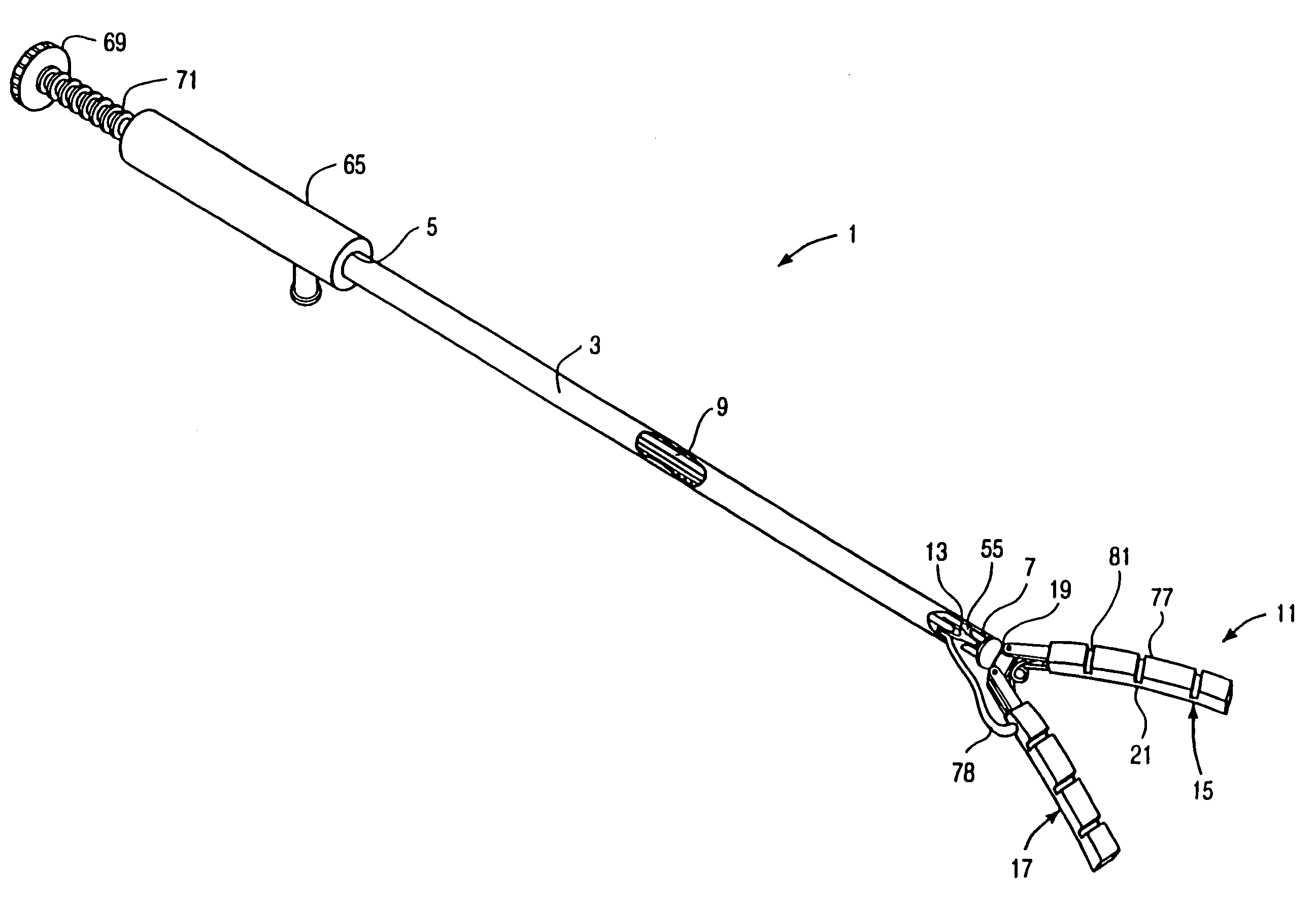
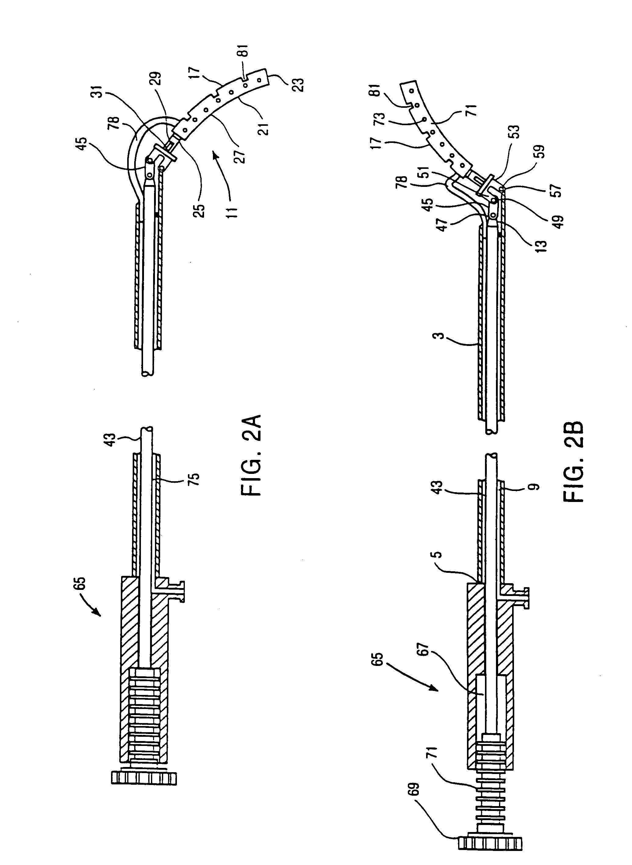
[0034]The system and method of the present invention for isolating a surgical site will now be described in detail. Referring to FIG. 1, an endoscopic device 1 includes a shaft 3 having a proximal end 5, a distal end 7 and an axial passage 9 therebetween. Shaft 3 is preferably a stainless steel tube having an outer diameter in the range of 2–10 mm, usually 4–8 mm, so as to fit within a cannula having an internal diameter in the range of 2–15 mm. Shaft 3 can also be introduced directly through a percutaneous incision in the patient. Shaft 3 has a length selected to reach a target site in a body cavity, such as the abdomen or thoracic cavity, and to extend sufficiently out of the body cavity to facilitate easy manipulation of endoscopic device1. Thus, shaft 3 should be at least between 10 cm and 40 cm and is preferably between 17 cm and 30 cm. It should be noted that although shaft 3 is shown as having a circular cross-sectional shape in the drawings, shaft 3 could alternatively have ...


PUM


Abstract

The invention provides a system and method for performing less-invasive surgical procedures within a body cavity. In a preferred embodiment, the invention provides a system and method for isolating a surgical site such as an anastomosis between an internal mammary artery and a coronary artery in a thoracoscopic coronary artery bypass grafting procedure. The system comprises a foot (11) pivotally coupled to the distal end of a shaft (3) by a linkage (13). The foot has first and second engaging portions (15, 17) with contact surfaces for engaging a tissue surface. The engaging portions are movable between an open position, where the contact surfaces are separated by a gap, and a collapsed position, where the foot is configured for delivery through the percutaneous penetration. An actuator, at the proximal end of the shaft, can be rotated to pivot the foot about a transverse axis so that the contact surfaces are oriented generally parallel to the surgical site to apply pressure to the tissue structure on both sides of the surgical site.

Description

CROSS REFERENCE TO RELATED APPLICATIONS[0001]This application is a continuation of U.S. patent application Ser. No. 10 / 259,146, filed on Sep. 27, 2002 U.S. Pat. No. 6,821,247, which is a continuation of U.S. patent application Ser. No. 09 / 678,763, filed on Oct. 3, 2000, now U.S. Pat. No. 6,482,151, which is a continuation of U.S. patent application Ser. No. 09 / 306,687, filed May 6, 1999, now U.S. Pat. No. 6,149,583, which is a continuation of application Ser. No. 09 / 062,911, filed Apr. 20, 1998, now U.S. Pat. No. 6,017,304, which is a continuation of U.S. patent application, Ser. No. 08 / 603,175 filed Feb. 20, 1996, now U.S. Pat. No. 5,807,243, which is a divisional of application Ser. No. 08 / 298,646 filed Aug. 31, 1994, now abandoned.FIELD OF THE INVENTION[0002]This invention relates generally to a system and method for performing less-invasive surgical procedures, and more specifically, to a system and method for isolating a surgical site such as the site of an anastomosis of a gra...

Claims


Application Information

Patent Timeline
Patent Type & Authority Patents(United States)
IPC IPC(8): A61B1/32A61B17/00A61B17/02A61B17/04A61B17/11
CPCA61B17/0469A61B17/0483A61B17/062A61B17/11A61B2017/1107A61B2017/00243A61B2017/0243
Inventor VIERRA, MARK A.ROTH, ALEX T.
Owner HEARTPORT
Why Eureka
Try Eureka