Ceramic weld insulator and metal weld gear combination for an improved micro weld head component of an orbital tube welding apparatus

a technology of ceramic insulators and metal weld gears, which is applied in the direction of soldering equipment, manufacturing tools,auxillary welding devices, etc., can solve the problems of inability to establish the proper arc gap, affecting the quality of welds, and difficulty in closely aligning the moving parts of mating, so as to reduce the expansion force, increase the duty cycle of the weld head, and reduce the expansion for

Inactive Publication Date: 2006-04-11
ARC MACHINES
View PDF2 Cites 10 Cited by
  • Summary
  • Abstract
  • Description
  • Claims
  • Application Information

AI Technical Summary

Benefits of technology

[0022]One advantage of the present invention is that the rotor carries the electrically conductive member within it and insulates the conductive member from other components. Since the electrically-conductive member is substantially insulated with ceramic by the rotor, undesirable arcing from the conductive member to other components is reduced.
[0023]Still further advantages of the present invention will become apparent to those of ordinary skill in the art upon reading and understanding the following detailed description of the preferred embodiments.
[0024]It is an object of the present invention to provide an improved automatic tube welding apparatus.
[0025]It is another object of the present invention to significantly increase the duty cycle of a weld head.
[0026]It is another object of the present invention to control the expansion during a duty cycle.
[0027]It is another object of the present invention to significantly reduce the expansion force on the ceramic insulator.

Problems solved by technology

Failure to establish the proper arc gap can compromise weld quality and penetration.
Also, orbital welding may be used where a tube or pipe to be welded cannot be rotated or readily rotated, or where space restrictions limit the physical size of the orbital welding equipment.
The tungsten gap changes as the weld gear heats up and causes inconsistent weld thickness.
The use of plastic as an insulator limits the duty cycle and does not expand at the same rate of the metal parts, making it difficult to closely align the mating moving parts.
When this happens the gear stops moving and causes a bad weld or breaks the internal drive components.
Another common problem found with the current design is an arcing between the weld gear and the collets that hold the tubes.
When this arcing occurred, it is very destructive to the components of the weld head and fixture block as well as the tubing being welded.
In addition to erratic arcing, other problems known to be commonly associated with current orbital welding processes include arc wandering, difficult arc starting, excessive electrode consumption, and oxidized weld deposit.
Another significant problem that has plagued automatic orbital tube welding involves the plastic insulator / housing, which holds all the parts together in an orbital weld assembly.

Method used


Image

  • Ceramic weld insulator and metal weld gear combination for an improved micro weld head component of an orbital tube welding apparatus
  • Ceramic weld insulator and metal weld gear combination for an improved micro weld head component of an orbital tube welding apparatus
  • Ceramic weld insulator and metal weld gear combination for an improved micro weld head component of an orbital tube welding apparatus

Examples


Embodiment Construction

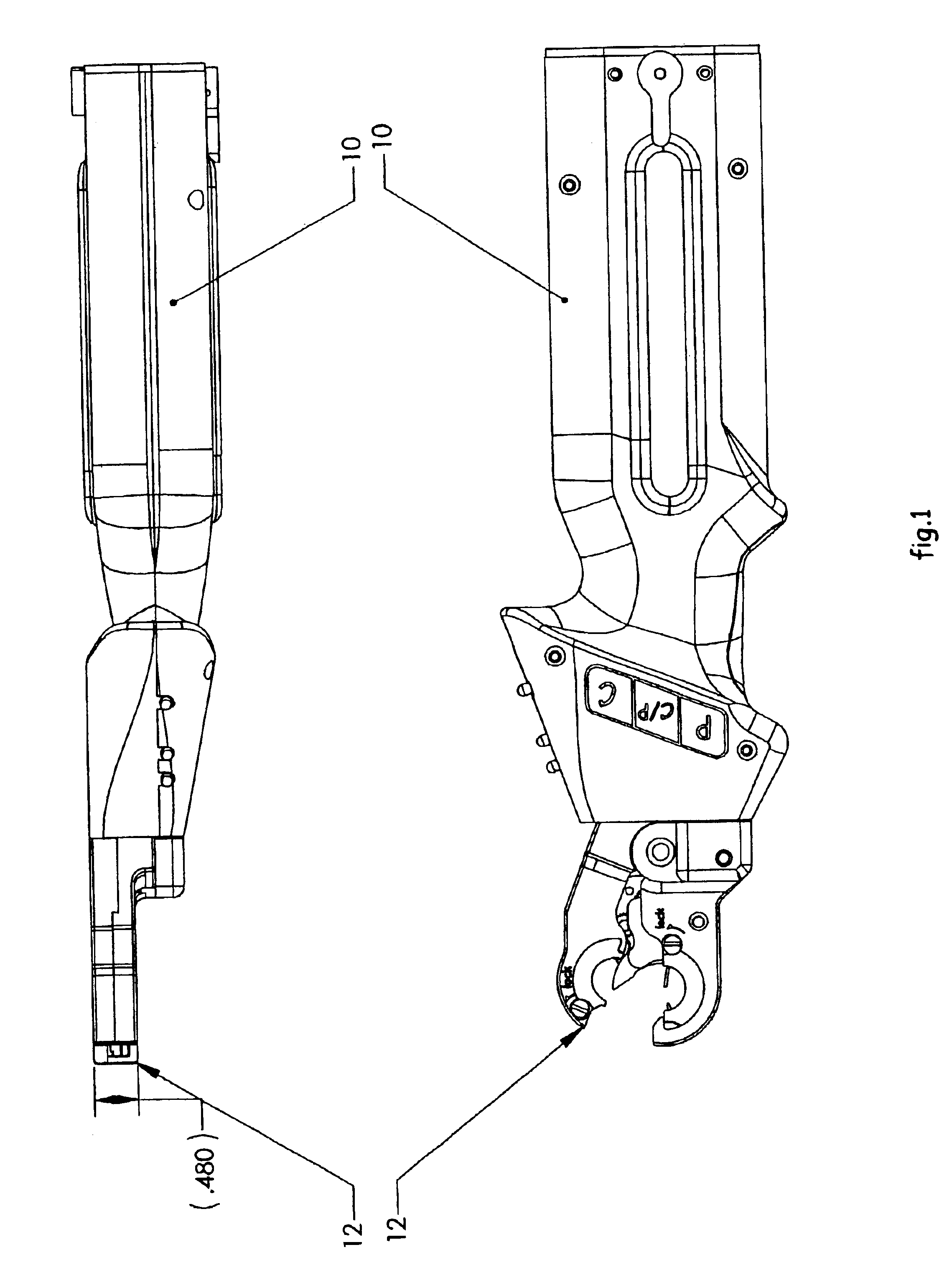
[0033]Referring to FIG. 1, the micro weld head apparatus 10 is shown in three different perspectives, including 2 different perspective view details of the micro weld head 12.

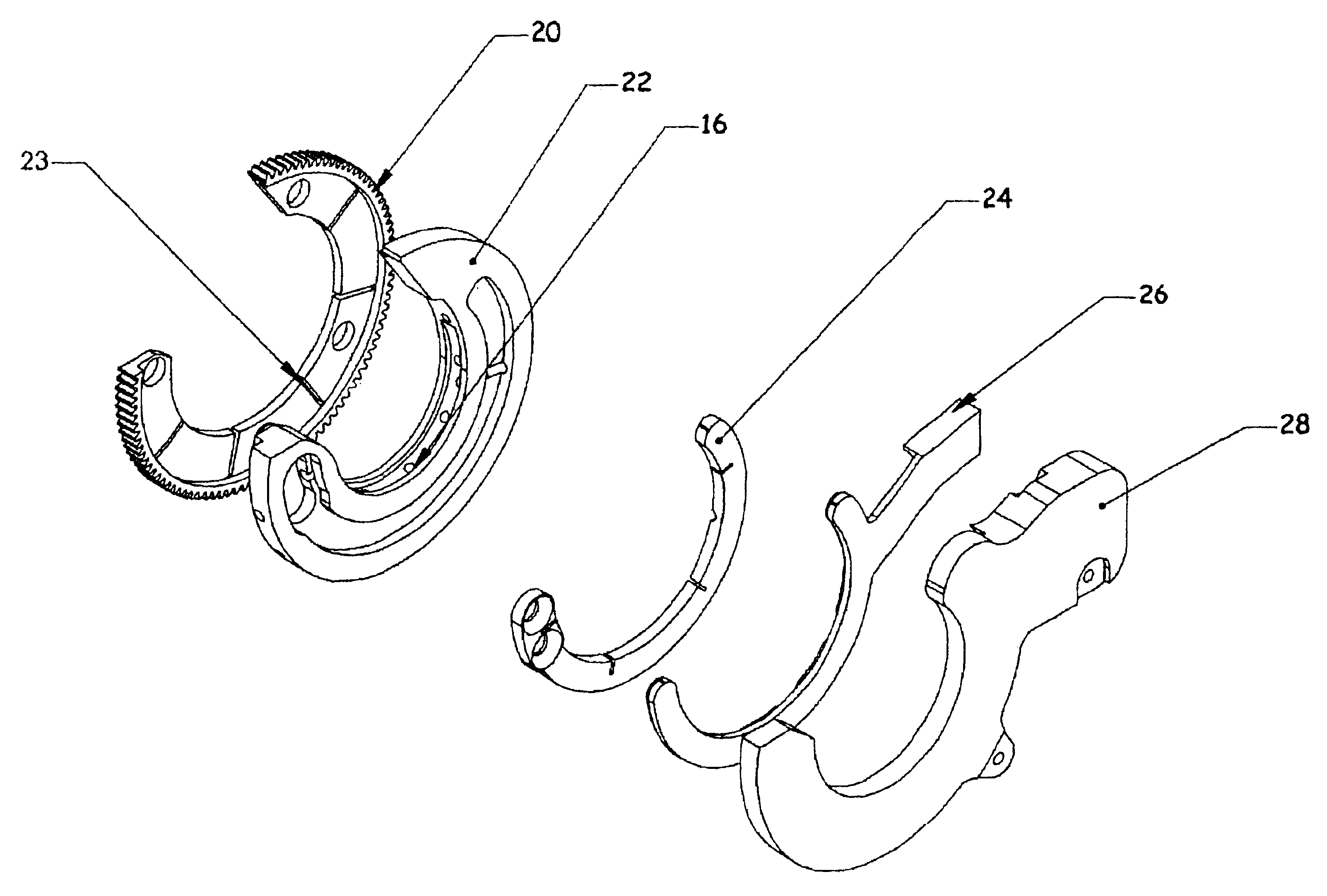
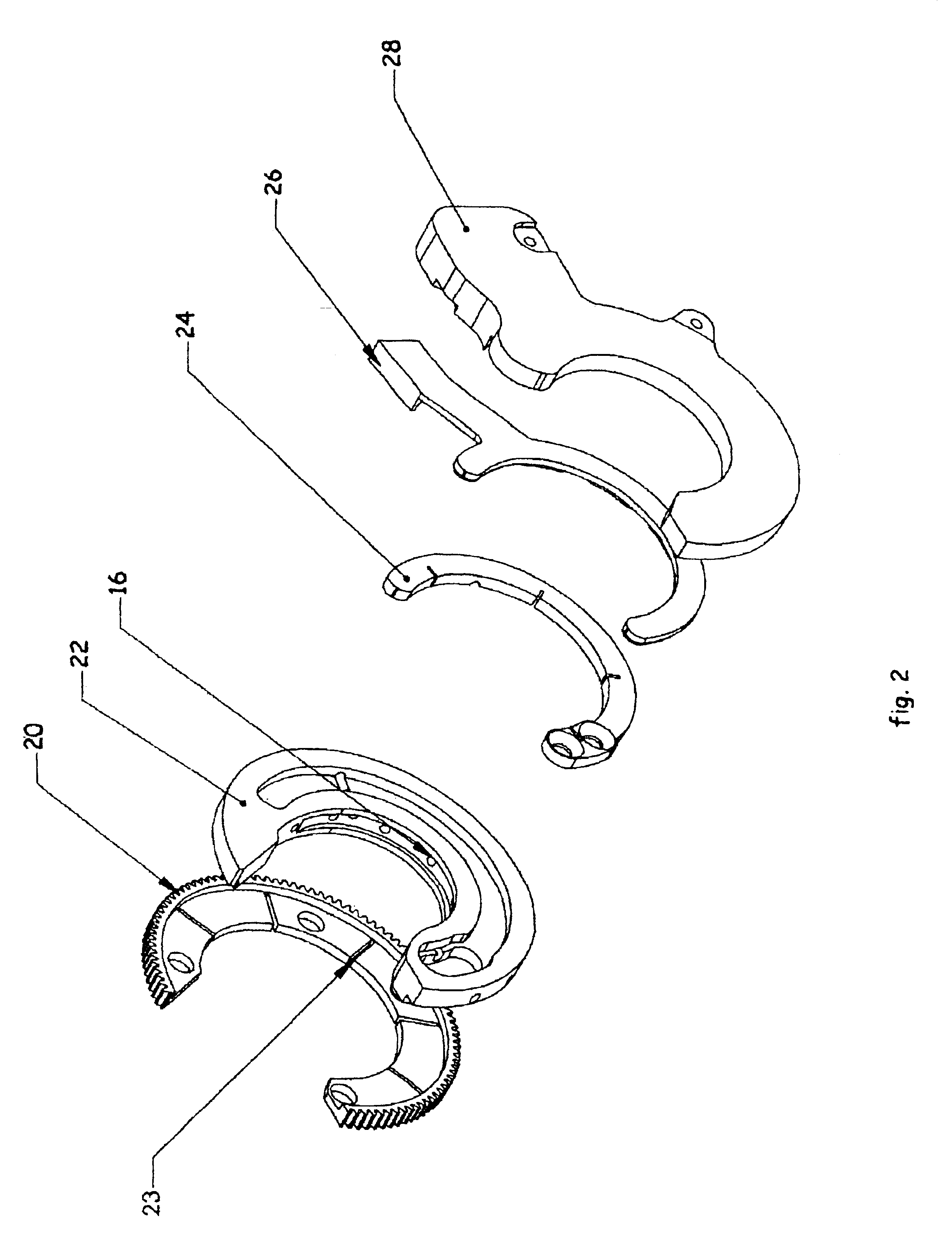
[0034]FIG. 2 shows the combination of materials that make up the micro weld head of the present invention. In the preferred embodiment, a weld gear assembly 16 includes a weld gear 20 in which is interlocked a ceramic insert 22.

[0035]The ceramic insert 22 provides an electrical insulation with minimal expansion (because of its ceramic construction). In the preferred embodiment, the weld gear 20, which drives the tungsten electrode (not shown) around the tubes or pipes to be welded, has slits 23, which allow for rapid heating and cooling with minimal effect to the concentricity of the path of the orbiting electrode relative to the tube, as is a serious problem with conventional weld gear assembly design.

[0036]In the preferred embodiment, the rotating electrical strip 24 is adjacent to the ceramic insert 22 but n...


PUM

PropertyMeasurementUnit
voltageaaaaaaaaaa
currentaaaaaaaaaa
arc voltageaaaaaaaaaa

Abstract

The invention is of an improvement to orbital welding heads and welding systems for welding pipe and tubing butt joints, consisting of a novel combination of materials, including a ceramic weld insulator and a metal weld gear. Such a combination, which has a greater dielectric strength than a plastic housing design, results in a more concentric tungsten travel path, increases the duty cycles of the weld head, minimizes erratic and wandering arcing, creates an electrical insulation yielding minimal expansion, allows for increased clamping surface for improved tube alignment, and provides a compact and very robust weld head.

Description

CITATION TO PARENT APPLICATION[0001]This is a continuation-in-part of Ser. No. 09 / 620,506, filed Jul. 20, 200, now U.S. Pat. No. 6,459,062 which issued Nov. 10, 2002, from which priority is claimed pursuant to 35 U.S.C. 120.BACKGROUND OF THE INVENTION[0002]1. Field of the Invention[0003]The present invention provides a new and improved ceramic insulator and metal weld gear for an improved micro weld head component of an orbital tube welding apparatus.[0004]2. Background Information[0005]Orbital tube welding was first used in the 1960s when the aerospace industry needed a superior joining technique for aircraft hydraulic and fuel system lines. This automated process was accomplished when the arc from a tungsten electrode was rotated accurately around the tubing weld joint. Two decades later orbital tube welding gained application in many other industries due to the development of smaller, more portable, solid-state power supplies, advanced control systems and other advancements. Adva...

Claims


Application Information

Patent Timeline
Patent Type & Authority Patents(United States)
IPC IPC(8): B23K9/12B23K9/028
CPCB23K9/0286B23K2201/06B23K2101/06
Inventor GUERRINA, MICHAEL
Owner ARC MACHINES
Why Eureka
Try Eureka