Apparatus for positioning an elevator tube

a technology for elevator tubes and apparatuses, which is applied in lighting and heating apparatus, muffle furnaces, furnaces, etc., can solve the problems of tube contact, temperature non-uniformity near the wafer perimeter, and loss of concentricity with the support structure, so as to reduce contact forces

Inactive Publication Date: 2006-04-11
AXCELIS TECHNOLOGIES
View PDF20 Cites 14 Cited by
  • Summary
  • Abstract
  • Description
  • Claims
  • Application Information

AI Technical Summary

Benefits of technology

[0005]A compliant, dynamic coupling for preventing the flow of gas into a pressurized chamber into which a rod extends through a chamber orifice and moves axially within the chamber. A bearing is mounted within the orifice and is disposed concentrically about the rod. An inner bearing surface is in close proximity to an outer surface of the rod. A gas port supplies pressurized gas into a gas curtain defined by the gas flow between the rod and the inner bearing surface. A compliant member is adjacent to the bearing for absorbing a force created when the rod moves into contact with the inner bearing surface to reduce contact forces created when the rod contacts the inner bearing surface. In an exemplary embodiment, the compliant member is a bellows, preferably made of metal.
[0006]An elevator tube positioning system for moving a wafer support within a process chamber features an elevator tube rigidly mounted at its base to a moveable carriage and protruding through an orifice into a process chamber. A gas curtain is established between the orifice and outer tube diameter to prevent incursion of ambient air into the chamber. A compliant, dynamic seal within the orifice engages the outer diameter of the tube to stabilize the tube's lateral position.

Problems solved by technology

The vibrations may cause the wafer to move relative to the support, thereby losing concentricity with the support structure.
Lack of concentricity results in temperature non-uniformity near the wafer perimeter.
However, low clearance between the bearing and the elevator tube increases the possibility that the elevator tube will contact the bearing and pick up contaminants from the bearing that may be carried into the processing chamber.

Method used


Image

  • Apparatus for positioning an elevator tube
  • Apparatus for positioning an elevator tube
  • Apparatus for positioning an elevator tube

Examples


Embodiment Construction

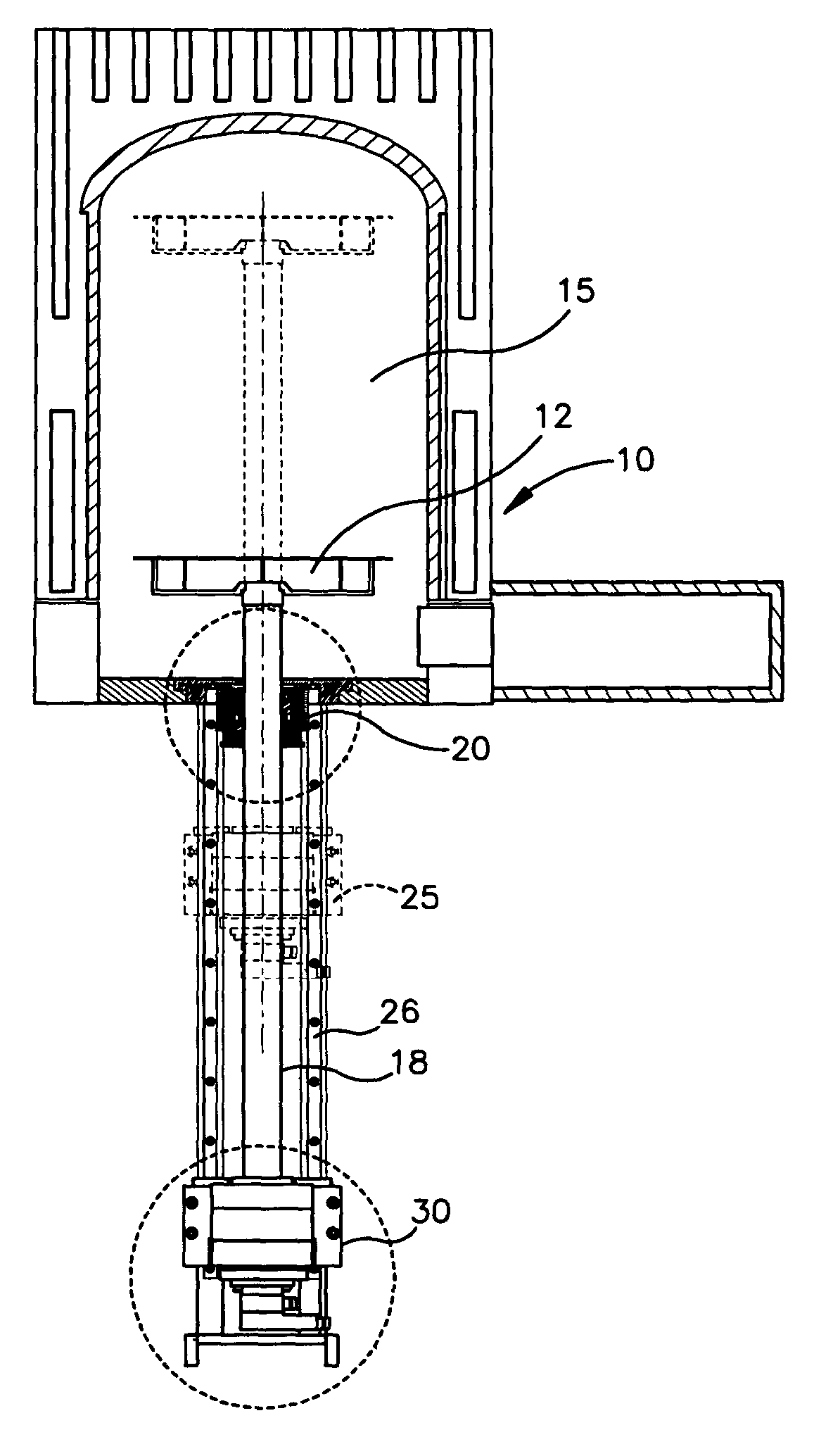
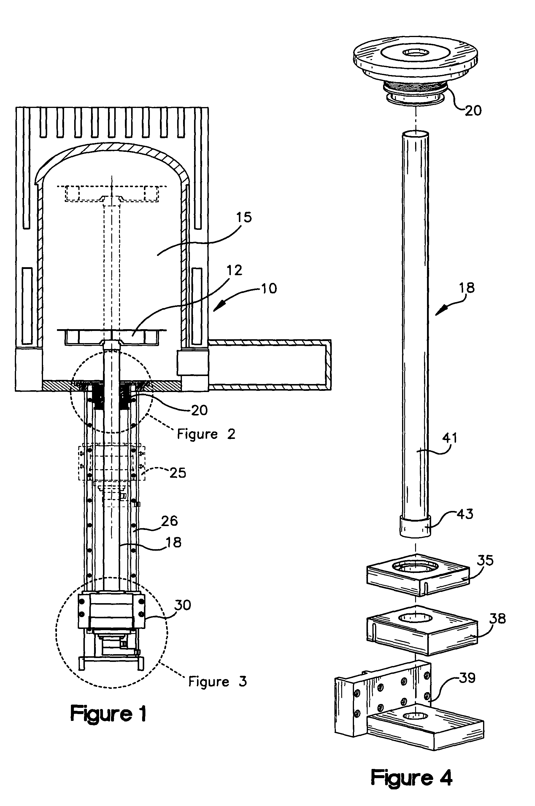
[0012]FIG. 1 illustrates a rapid thermal processing system 10 that uses a cylindrical hot wall system to thermally process semiconductor wafers. A wafer (not shown) is placed on a wafer support indicated generally as reference numeral 12. The wafer is moved vertically through a process chamber having a temperature gradient created by heating elements behind the chamber walls. The wafer support 12 is connected to an elevator tube assembly 18 that protrudes through an orifice in the chamber floor. The elevator tube is connected via a pair of flexures indicated generally as 30 (shown separately as 35, 38 in FIG. 4) to a moveable carriage having a base support 39 (FIG. 4) that traverses a set of rails 26 to move the elevator tube 18 and wafer support 12 along a vertical excursion within the process chamber 15.

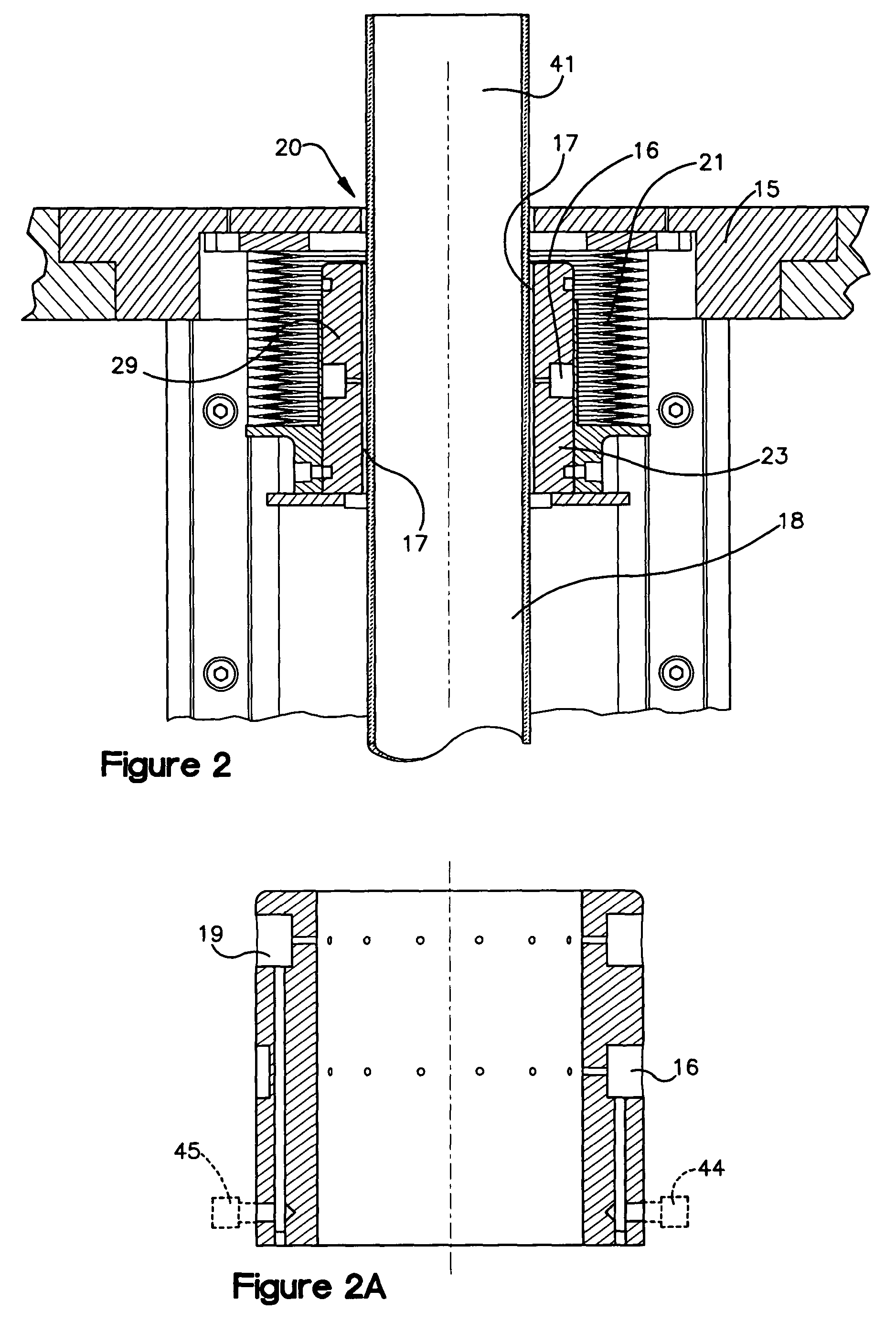
[0013]A bearing assembly 20 surrounds the elevator tube at the bottom of the process chamber and provides a compliant, dynamic coupling between the tube and the chamber that minimi...


PUM

PropertyMeasurementUnit
contact forcesaaaaaaaaaa
of rotationaaaaaaaaaa
temperatureaaaaaaaaaa

Abstract

A wafer support position control mechanism selectively positions a semiconductor wafer along an axis of excursion within a process chamber. An elevator tube protrudes through an orifice in the chamber surface and is connected at a first distal end to the wafer support. A compliant, dynamic seal within the orifice engages the elevator tube to form a gas curtain within a gap between the seal and the elevator tube to seal the process chamber. A moveable carriage is connected to the elevator tube at a second distal end for moving the wafer support along the axis of excursion. Rigid mechanical structure couples the second distal end of the elevator tube to the moveable carriage.

Description

TECHNICAL FIELD[0001]The present invention relates generally to the field of semiconductor thermal processing systems, and more specifically to a vertical rapid thermal processing unit that includes an elevator assembly for positioning a wafer within the processing unit.BACKGROUND OF THE INVENTION[0002]Thermal processing systems are widely used in various stages of semiconductor fabrication. Basic thermal processing applications include chemical deposition, diffusion, oxidation, annealing, silicidation, nitridation, and solder re-flow processes. Vertical rapid thermal processing (RTP) systems comprise a vertically oriented processing chamber which is heated by a heat source such as a resistive heating element or a bank of high intensity light sources. An elevator structure is controlled to move a wafer on a wafer support vertically within the processing chamber. In some RTP systems, the heat sources create a temperature gradient within the processing chamber and temperature ramp-up ...

Claims


Application Information

Patent Timeline
Patent Type & Authority Patents(United States)
IPC IPC(8): F27B5/14F27D11/00H01L21/00H01L21/324H01L21/677
CPCH01L21/67751H01L21/67748H01L21/67126H01L21/324
Inventor PHARAND, MICHELDURANT, THOMAS L.EIRIKSSON, ARIGUELER, RICHARD
Owner AXCELIS TECHNOLOGIES
Why Eureka
Try Eureka