
Light emitting diodes including pedestals

a technology of light-emitting diodes and pedestals, which is applied in the direction of basic electric elements, semiconductor devices, electrical equipment, etc., can solve the problems of inability to maintain the effect of these shaping techniques, difficulty in using conventional techniques for light extraction, and difficulty in using thick p-type window layers, etc., to improve light extraction and light extraction

Inactive Publication Date: 2006-04-11
CREE INC
View PDF93 Cites 74 Cited by
  • Summary
  • Abstract
  • Description
  • Claims
  • Application Information

AI Technical Summary

Benefits of technology

[0024]Sawing a plurality of intersecting grooves and/or reactive etching an array of via holes into the first face may be used for light emitting diodes that include a silicon carbide or non-silicon carbide substrate to allow improved light extractio...

Problems solved by technology

Unfortunately, the effectiveness of these shaping techniques may not be maintained as the chip dimensions are scaled up for higher power / intensity and / or other applications.
In such silicon carbide LEDs or gallium nitride LEDs on silicon carbide, it may be difficult to use conventional techniques for light extraction.
For example, it may be difficult to use thick p-type window layers because of the relatively low growth rate of gallium nitride.
Also, although such LEDs may benefit from the use of Bragg reflectors and / or substrate removal techniques, it may be difficult to fabricate a reflector between the substrate and the gallium nitride diode region and / or to etch away at least part of the silicon carbide substrate.

Method used


Image

  • Light emitting diodes including pedestals
  • Light emitting diodes including pedestals
  • Light emitting diodes including pedestals

Examples


Embodiment Construction

[0035]The present invention now will be described more fully hereinafter with reference to the accompanying drawings, in which preferred embodiments of the invention are shown. This invention may, however, be embodied in many different forms and should not be construed as limited to the embodiments set forth herein. Rather, these embodiments are provided so that this disclosure will be thorough and complete, and will fully convey the scope of the invention to those skilled in the art. In the drawings, the thickness of layers and regions are exaggerated for clarity. Like numbers refer to like elements throughout. It will be understood that when an element such as a layer, region or substrate is referred to as being “on” or extending “onto” another element, it can be directly on or extend directly onto the other element or intervening elements may also be present. In contrast, when an element is referred to as being “directly on” or extending “directly onto” another element, there are...


PUM


Abstract

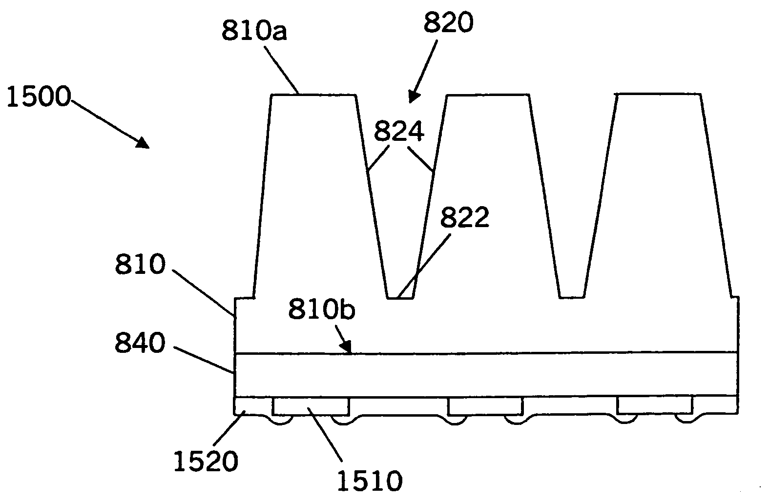
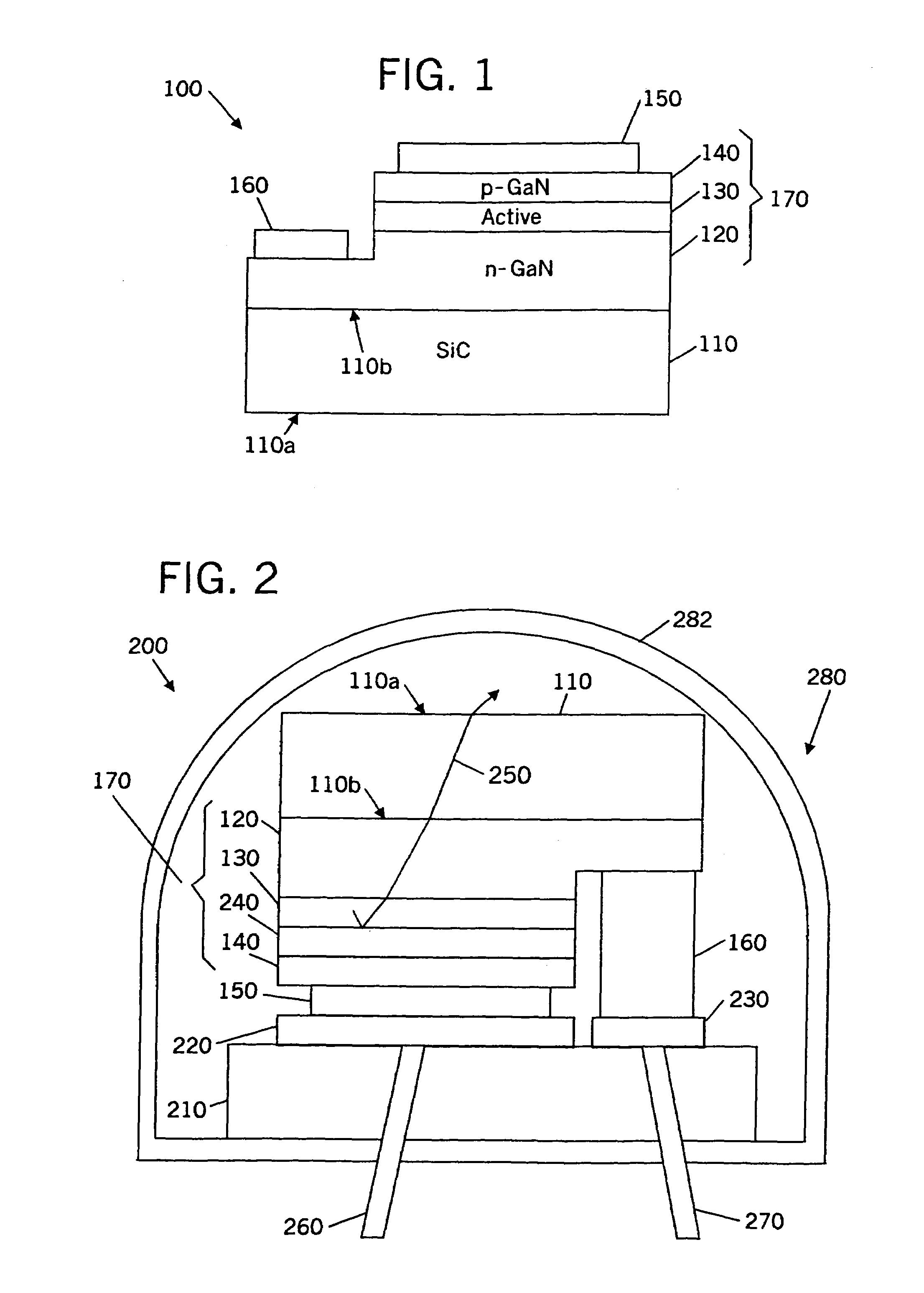
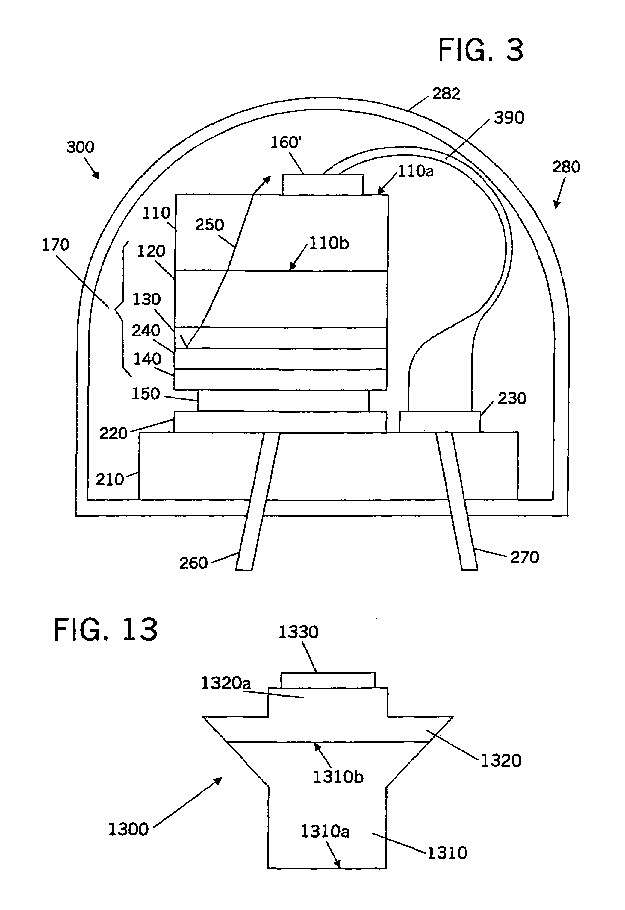
Light emitting diodes include a substrate having first and second opposing faces and that is transparent to optical radiation in a predetermined wavelength range and that is patterned to define, in cross-section, a plurality of pedestals that extend into the substrate from the first face towards the second face. A diode region on the second face is configured to emit light in the predetermined wavelength range, into the substrate upon application of voltage across the diode region. A mounting support on the diode region, opposite the substrate is configured to support the diode region, such that the light that is emitted from the diode region into the substrate, is emitted from the first face upon application of voltage across the diode region. The first face of the substrate may include therein a plurality of grooves that define the plurality of triangular pedestals in the substrate. The grooves may include tapered sidewalls and / or a beveled floor. The first face of the substrate also may include therein an array of via holes. The via holes may include tapered sidewalls and / or a floor.

Description

[0001]This application is a divisional of application Ser. No. 10 / 057,821, filed Jan. 25, 2002, entitled Light Emitting Diodes Including Modications for Light Extraction and Manufacturing Methods Therefor, now U.S. Pat. No. 6,791,119, and claims the benefit of Provisional Application Ser. No. 60 / 265,707, filed Feb. 1, 2001 entitled Light Emitting Diode With Optically Transparent Silicon Carbide Substrate, and Provisional Application Ser. No. 60 / 307,235, filed Jul. 23, 2001, entitled Light Emitting Diodes including Modifications for Light Extraction and Manufacturing Methods Therefor, the disclosures of all of which are hereby incorporated herein by reference in their entirety as if set forth fully herein.STATEMENT OF FEDERAL SUPPORT[0002]This invention was made possible with government support under grant number 70NANB8H4022 from the National Institute of Standards and Technology (Advanced Technology Program). The United States government has certain rights to this invention.FIELD O...

Claims


Application Information

Patent Timeline
IPC IPC(8): H01L33/00H01L33/10H01L33/20H01L33/22H01L33/40H01L33/60H01L33/62
CPCH01L33/20H01L33/405H01L33/10H01L33/22H01L33/60H01L33/62H01L2924/12041H01L2224/48091H01L2224/73265H01L2924/12032H01L2924/10253H01L2924/01079H01L2924/01322H01L2224/32014H01L2924/00014H01L2924/00
Inventor SLATER, JR., DAVID B.GLASS, ROBERT C.SWOBODA, CHARLES M.KELLER, BERNDIBBETSON, JAMESTHIBEAULT, BRIANTARSA, ERIC J.
Owner CREE INC
Features
  • Generate Ideas
  • Intellectual Property
  • Life Sciences
  • Materials
  • Tech Scout
  • Unparalleled Data Quality
  • Higher Quality Content
  • 60% Fewer Hallucinations
Learn More