Optical pulse generator and optical pulse testing instrument and method

a technology of optical pulse generator and optical pulse, which is applied in the direction of optical elements, instruments, electromagnetic transceivers, etc., can solve the problems of expensive optical switches

Inactive Publication Date: 2006-04-11
ADVANTEST CORP
View PDF15 Cites 10 Cited by
  • Summary
  • Abstract
  • Description
  • Claims
  • Application Information

AI Technical Summary

Benefits of technology

[0019]An object of the present invention is to provide an optical pulse generator which can be formed without using expensive optical parts and requires no complicated device control, and an optical pulse testing apparatus using the optical pulse generator and an optical pulse testing method.
[0032]According to the present invention, in the optical pulse testing method comprising the steps of: supplying a probe optical pulse an optical fiber-to-be-measured; detecting reflected light of the probe optical pulse entered into the optical fiber-to-be-measured that has been reflected while propagating through the optical fiber-to-be-measured; and analyzing a light transmission state of the optical fiber-to-be-measured, based on a detection result of the reflected light, an excitation optical pulse is supplied to a ring optical path including an optical fiber with a rare earth element added to excite the optical fiber, and the circulating optical pulse which is circulating through the ring optical path is branched as the probe optical pulse; the circulating optical pulse circulating through the ring optical path is detected; and a timing of starting the analysis of a light transmission state of the optical fiber-to-be-measured is controlled based on a detection result of the circulating optical pulse. Thus, the optical pulse generator can be constituted without using expensive optical parts, and the light transmission state of the optical fiber-to-be-measured can be measured without requiring complicated device control.

Problems solved by technology

On the other hand, the use of the variable wavelength ring laser shown in FIG. 11 to simplify the timing control of the optical pulse testing apparatus requires the expensive optical switch 136 for generating optical pulses.

Method used


Image

  • Optical pulse generator and optical pulse testing instrument and method
  • Optical pulse generator and optical pulse testing instrument and method
  • Optical pulse generator and optical pulse testing instrument and method

Examples


first embodiment

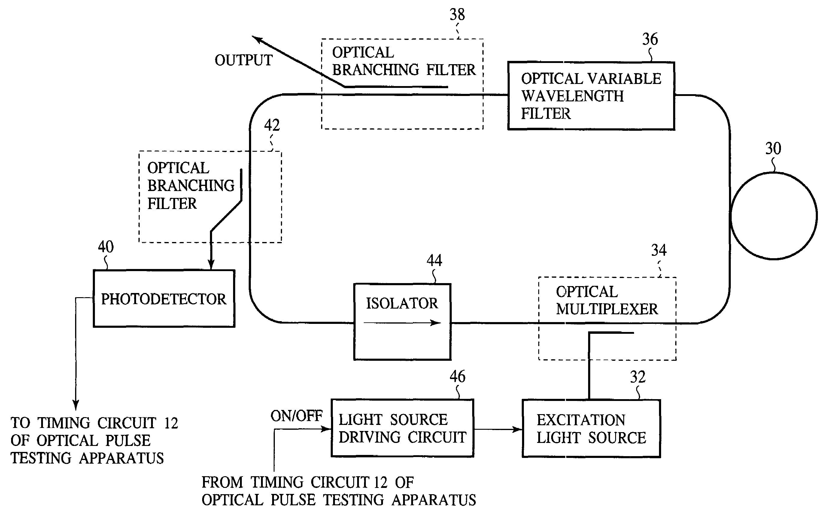
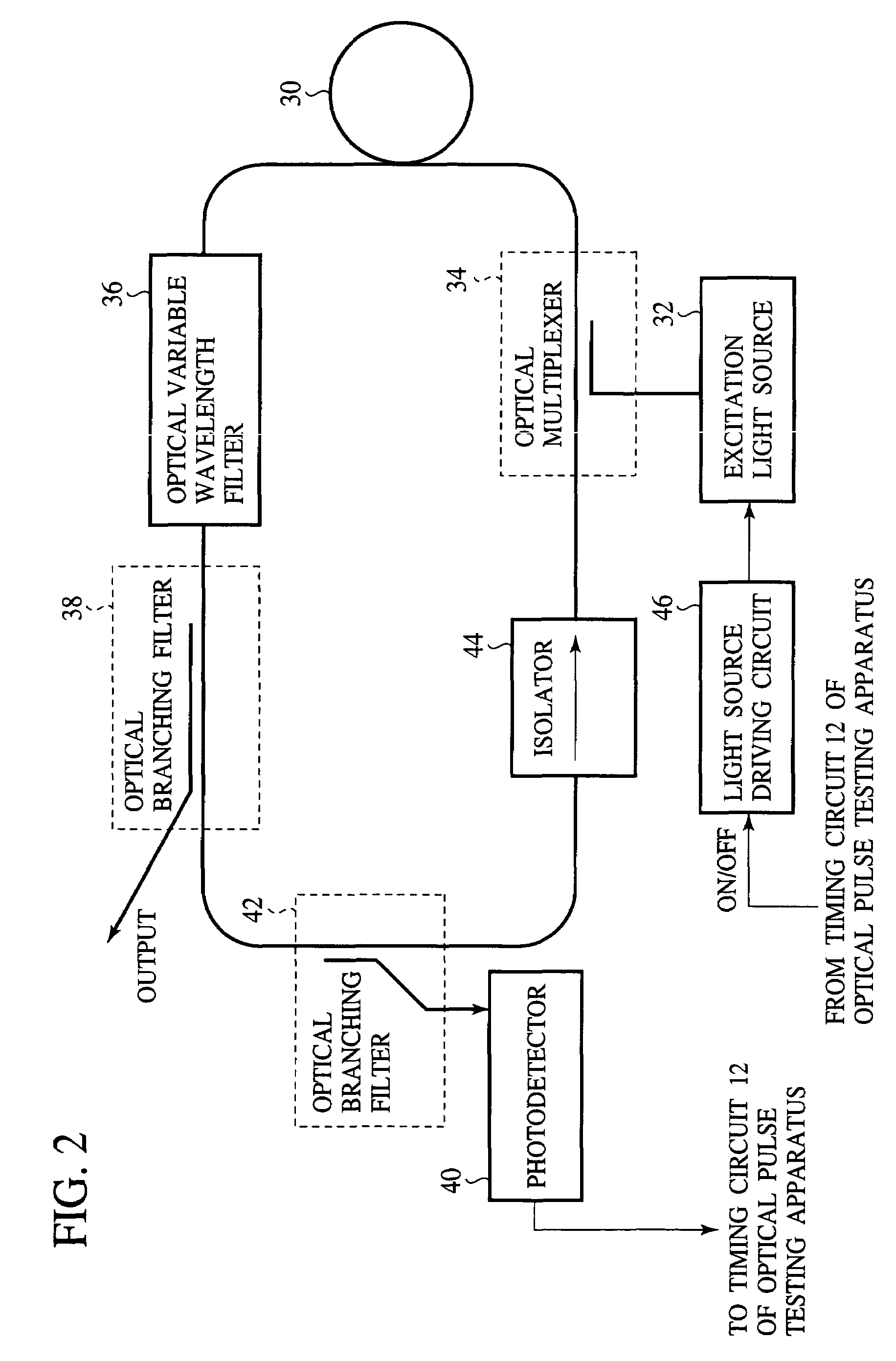
[0044]The optical pulse generator according to a first embodiment of the present invention, and the optical pulse testing apparatus using the same and the optical pulse testing method will be explained with reference to FIGS. 1 to 3. FIG. 2 is a block diagram of a structure of the optical pulse generator. FIGS. 3(a)–3(f) are timing charts showing the control operations of the optical pulse testing apparatus.

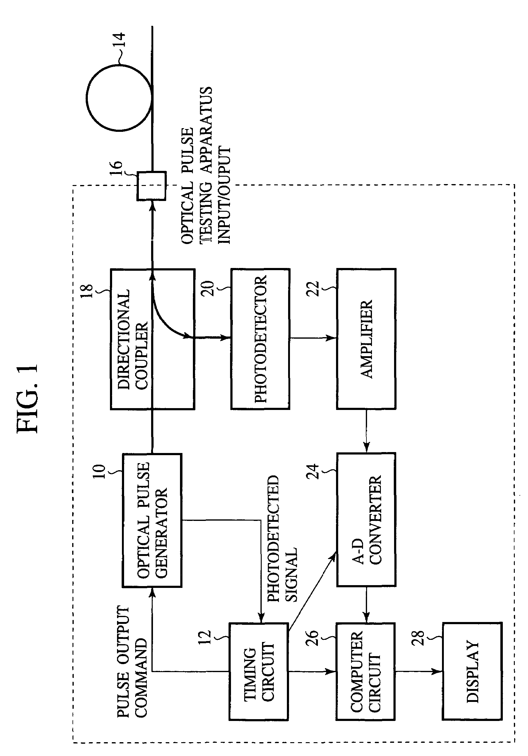
[0045]First, the structure of the optical pulse testing apparatus according to the present embodiment will be explained with reference to FIG. 1.

[0046]The optical pulse generator 10 used as a pulse light source of the optical pulse testing apparatus is connected to a timing circuit 12 which drives the optical pulse generator 10. An optical fiber-to-be-measured 14 is connected to the output of the optical pulse generator 10 via a directional coupler 18 and an input / output connector 16. The directional coupler 18 is connected to a photodetector 20 which detects light which has been...

second embodiment

[0082]The optical pulse generator, and the optical pulse testing apparatus and method according to a second embodiment of the present invention will be explained with reference to FIGS. 4 and 5(a)–5(f). FIG. 4 is a schematic diagram showing a structure of the optical pulse generator according to the present embodiment. FIGS. 5(a)–5(f) are timing charts of showing the control timings and waveforms of the optical pulse testing apparatus. The same members of the present embodiment as those of the optical pulse generator and the optical pulse testing apparatus according to the first embodiment are represented by the same reference numbers to simplify their explanation.

[0083]The structure of the optical pulse generator shown in FIG. 4 according to the present embodiment is substantially the same as that of the first embodiment, and the structure of the optical pulse testing apparatus is also the same. The optical pulse generator 10 according to the present embodiment is characterized in ...

third embodiment

[0090]The optical pulse generator, and the optical pulse testing apparatus and method according to a third embodiment of the present invention will be explained with reference to FIG. 6. FIG. 6 is a schematic diagram showing a structure of the optical pulse generator according to the present embodiment. The same members of the present embodiment as those of the optical pulse generator and the optical pulse testing apparatus according to the first embodiment are represented by the same reference numbers to simplify their explanation.

[0091]Optical pulses given by the optical pulse generator according to the first embodiment have output peaks which can be controlled by excitation intensities of the excitation light source 32, and output pulse frequencies which can be controlled by excitation pulse repetition frequencies of the excitation light source 32. However, an output pulse width is substantially determined by the optical parts constituting the optical pulse generator 10.

[0092]The...


PUM


Abstract

An optical pulse testing apparatus incorporating an optical pulse generator composed of low cost components. The optical pulse testing apparatus comprises: a ring optical path including an optical fiber 30 with a rare earth element added to; an excitation light source 32 which enters excitation optical pulses into the optical fiber 30; an optical branching filter 38 for branching the circulating optical pulses circulating through the ring optical path to emit output optical pulses; and a photodetector 40 for detecting the circulating optical pulses circulating through the ring optical path to obtain signals indicative of a light intensity and a generation timing of the circulating optical pulses. Thus, the optical pulse generator, and the optical pulse testing apparatus and method using the optical pulse generator require no expensive optical parts and complicated device control.

Description

[0001]This application claims the benefit of foreign filing priority under 35 U.S.C. 109(e) based on Japanese Patent Application No. 2000-313691, filed Oct. 13, 2000.FIELD OF THE INVENTION[0002]The present invention relates to an optical pulse generator which is usable as a pulse light source of an optical pulse testing apparatus, and an optical pulse testing apparatus using the optical pulse generator and an optical pulse testing method.BACKGROUND ART[0003]Broken points of optical fiber cables, distributions of transmission losses, coupling losses, etc. can be measured by an optical pulse testing apparatus (OTDR; Optical Time Domain Reflectometer).[0004]The structure of a conventional optical pulse testing apparatus will be explained with reference to FIG. 8. FIG. 8 is a block diagram of the structure of the optical pulse testing apparatus.[0005]The conventional optical pulse testing apparatus includes a semiconductor laser 100 as a means for generating optical pulses as a probe. T...

Claims


Application Information

Patent Timeline
Patent Type & Authority Patents(United States)
IPC IPC(8): H04B10/12H01S3/067H04B10/40H04B10/50H04B10/508H04B10/60
CPCH01S3/06791
Inventor KANOU, EIJI
Owner ADVANTEST CORP
Why Eureka
Try Eureka