Endoscope objective lens

a technology of endoscope and objective lens, which is applied in the field of endoscope objective lens, can solve the problems of difficult operation of endoscope, difficult to achieve high precision, and the total length of the objective lens may become too long, and achieve the effect of narrow diameter and high optical performan

Inactive Publication Date: 2006-04-11
FUJI PHOTO OPTICAL CO LTD
View PDF8 Cites 69 Cited by
  • Summary
  • Abstract
  • Description
  • Claims
  • Application Information

AI Technical Summary

Benefits of technology

[0003]The present invention relates to an endoscope objective lens that has a comparatively narrow diameter, provides high optical performance, and is compact.

Problems solved by technology

However, in such a case, there is concern that the total length of the objective lens may become too long, making the endoscope difficult to operate.
However, since the objective lens of the above-mentioned Japanese Laid-Open Patent Application H02-176612 has a comparatively large positive refractive power in the third lens element, an aspheric surface must be introduced in order to correct various aberrations such as coma and astigmatism, making it difficult to achieve a high precision due to problems in processing.
On the other hand, with the objective lens described in the above-mentioned Japanese Laid-Open Patent Application H09-68647, correction of spherical aberration is not always sufficient due to the placement of the diaphragm and the amount of refractive power of the first lens element.

Method used


Image

  • Endoscope objective lens
  • Endoscope objective lens
  • Endoscope objective lens

Examples


embodiment 1

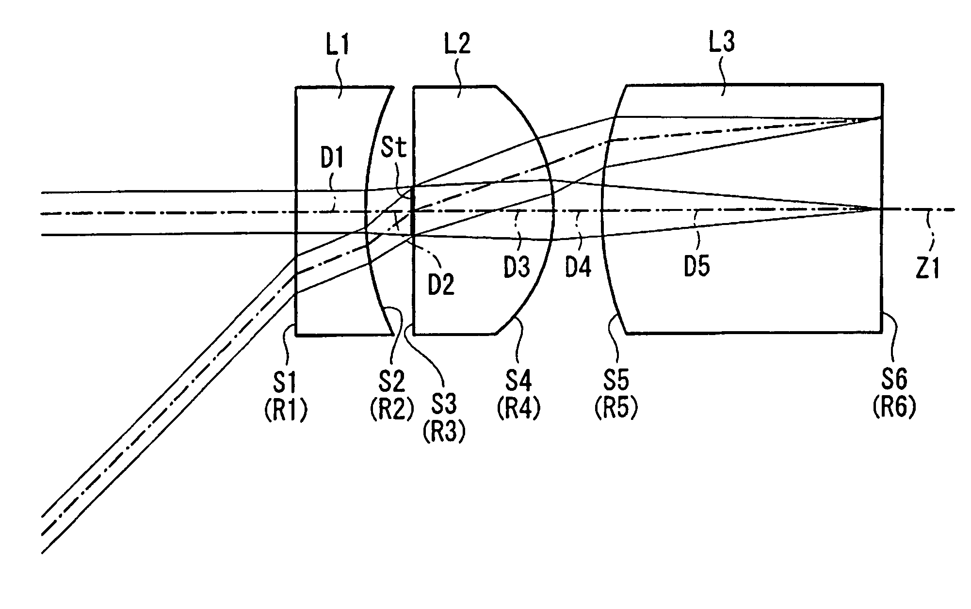
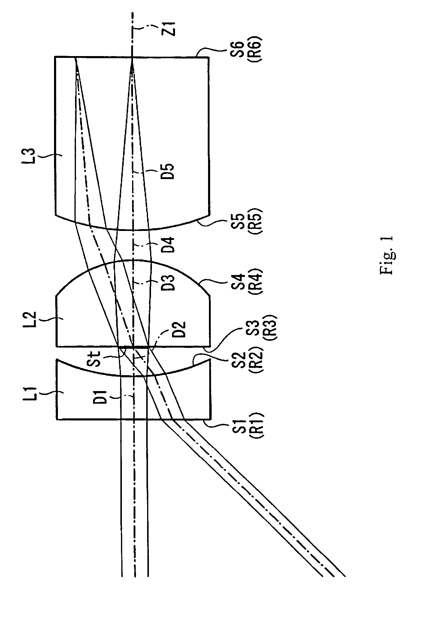
[0040]FIG. 1 is a cross-section that illustrates the lens element configuration according to Embodiment 1 of the present invention.

[0041]Table 1 below lists the surface number #, in order from the object side, the radius of curvature R (in mm) of each surface, the on-axis surface spacing D (in mm) between surfaces, as well as the refractive index Nd and the Abbe number νd (both at the d-line of λ=587.6 nm) of each lens element of Embodiment 1. In the bottom portion of the table are listed the focal length and the object distance (as measure from the object to surface #1 S1) of the endoscope objective lens of this embodiment.

[0042]

TABLE 1#RDNdνd1∞0.27501.9068021.221.10000.18603∞0.55001.8830040.94−0.62000.192051.23701.15061.8830040.96∞f = 0.5 mmObject distance = 10 mm

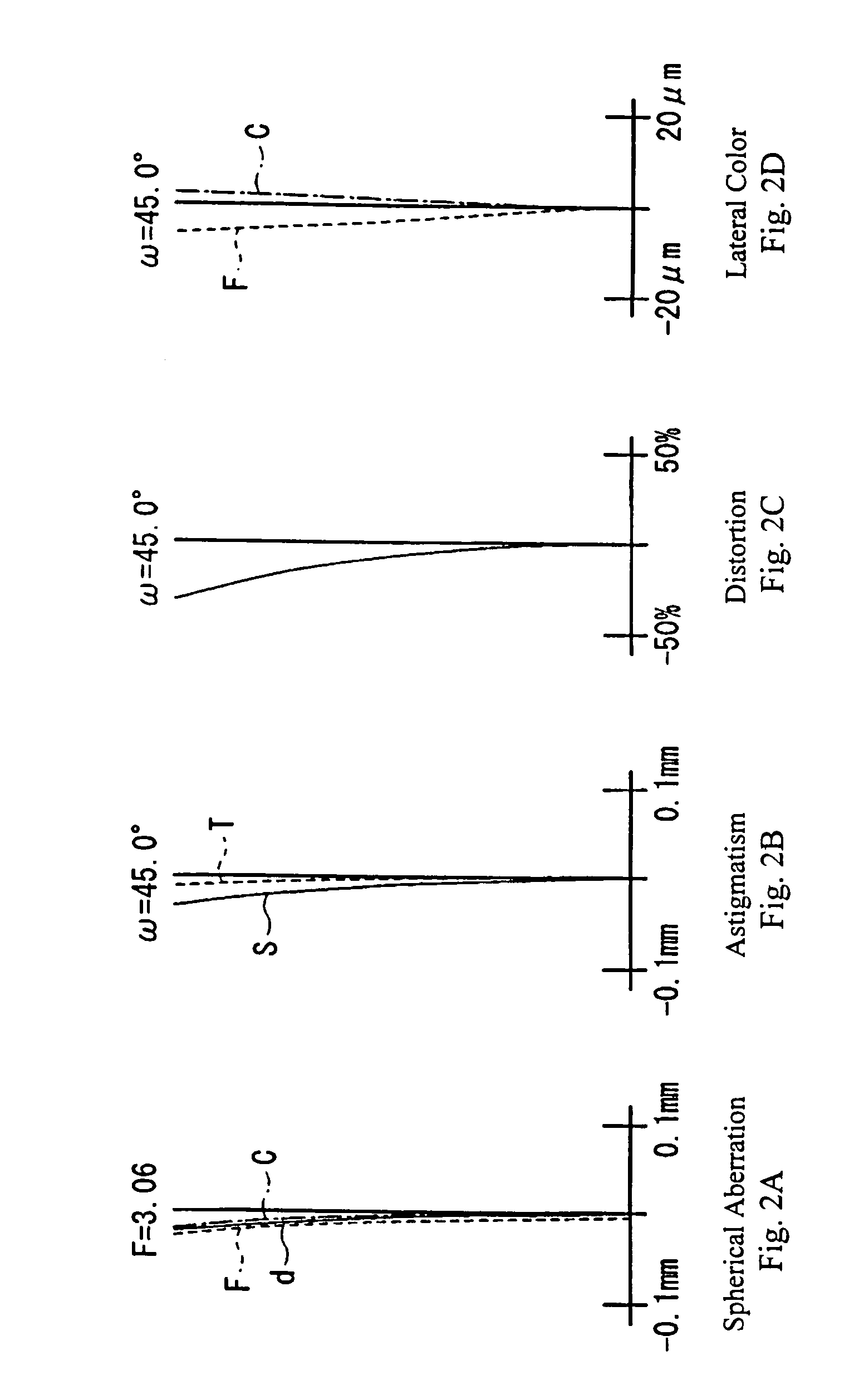
[0043]FIGS. 2A–2D show the spherical aberration, astigmatism, distortion, and lateral color, respectively, for the endoscope objective lens of Embodiment 1. Each figure indicates the aberration for the d-line as the stand...

embodiment 2

[0045]FIG. 4 is a cross-section that illustrates the lens element configuration according to Embodiment 2 of the present invention.

[0046]Table 2 below lists the surface number #, in order from the object side, the radius of curvature R (in mm) of each surface, the on-axis surface spacing D (in mm) between surfaces, as well as the refractive index Nd and the Abbe number νd (both at the d-line of λ=587.6 nm) of each lens element of Embodiment 2. In the bottom portion of the table are listed the focal length and the object distance (as measure from the object to surface #1 S1) of the endoscope objective lens of this embodiment.

[0047]

TABLE 2#RDNdνd1∞0.33501.9068021.221.17200.39303∞0.67001.8830040.94−0.75300.167051.33901.36211.8830040.96∞f = 0.5 mmObject distance = 10 mm

[0048]FIGS. 5A–5D show the spherical aberration, astigmatism, distortion, and lateral color, respectively, for the endoscope objective lens of Embodiment 2. Each figure indicates the aberration for the d-line as the stand...


PUM


Abstract

An endoscope objective lens with a three-group, three lens element construction, is formed of, in order from the object side, a first lens element having either a negative meniscus shape or a plano-concave shape with its concave surface on the image side, a stop, a positive second lens element having a plano-convex shape with its convex surface on the image side, and a positive third lens element having a plano-convex shape with its convex surface on the object side. The stop is positioned on or in contact with the object-side surface of the second lens element so that the endoscope objective lens is substantially telecentric. Specified conditions are satisfied in order to reduce aberrations and make the manufacture of the endoscope objective lens easier and less expensive.

Description

BACKGROUND OF THE INVENTION[0001]Endoscopes are conventionally used at medical treatment facilities for observing or providing treatment within the body of a patient. The objective lens currently proposed for use in this type of endoscope has a back-focus of zero, with the image-side surface of the final lens element in contact with an end surface of a fiber optical bundle of an image guide, as in Japanese Laid-Open Patent Application H02-69710. However, in such a case, there is concern that the total length of the objective lens may become too long, making the endoscope difficult to operate. Therefore, an objective lens disclosed in, for example, Japanese Laid-Open Patent Application H02-176612 has been proposed as an objective lens with a short focus adjustment space. Further, the objective lens described in, for example, Japanese Laid-Open Patent Application H09-68647 discloses a compact, three lens element construction.[0002]However, since the objective lens of the above-mention...

Claims


Application Information

Patent Timeline
Patent Type & Authority Patents(United States)
IPC IPC(8): G02B21/02G02B23/24
CPCG02B23/243G02B9/12
Inventor MIYANO, HITOSHI
Owner FUJI PHOTO OPTICAL CO LTD
Why Eureka
Try Eureka