
Method and apparatus to control pole tip protrusion

a technology of pole tip and protrusion, which is applied in the field of methods and apparatus to control pole tip protrusion, can solve the problems of large risk, protrusion of the tip towards the surface of the medium, and the effect of relatively long time-scale ambient temperature correction, reducing the magnitude of write current, and low flying height in the disk driv

Inactive Publication Date: 2006-04-11
MAXTOR
View PDF29 Cites 16 Cited by
  • Summary
  • Abstract
  • Description
  • Claims
  • Application Information

AI Technical Summary

Benefits of technology

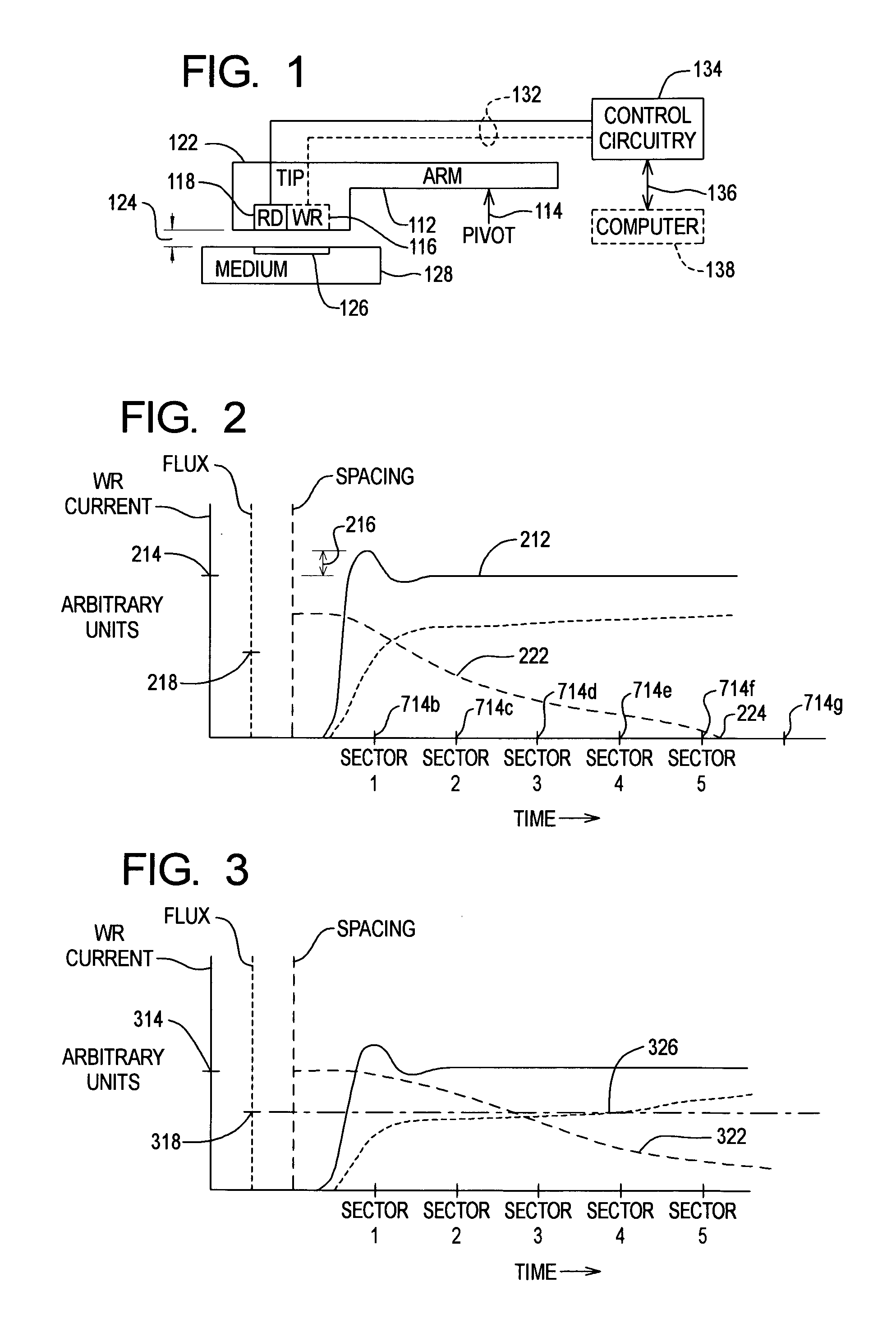
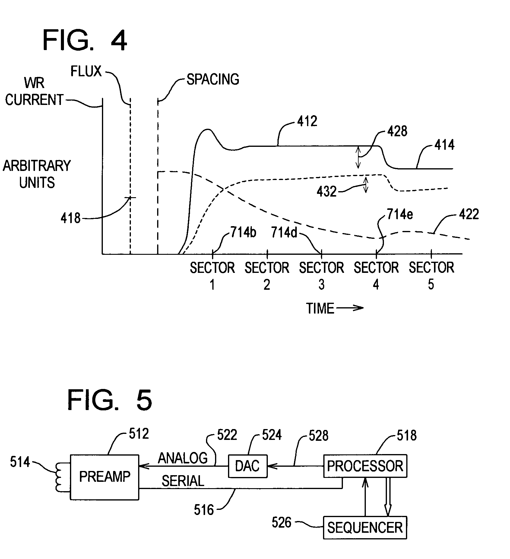
[0011]According to one aspect of the present invention, the magnitude of a write current is changed within a relatively short period (i.e., a relatively short period from the initiation of the write current until write current adjustment begins). In one aspect, write current is changed within the period of a single write operation. For example, the write current may be provided with the first magnitude while performing a write on (preferably contiguous) sectors 1 through K and a different (preferably lower) write current is used for the portion of the (same) write operation which is performed on disk sectors K+1 through N. Without wishing to be bound by any theory, it is believed useful to define or select the value of K (in one embodiment) so as to be related to the pole tip protrusion time constant. In other embodiments, other time-variations of write current within a write operation (“profiles”) can be used, such as providing more than two different values of write current within a single write operation, providing substantially continuously varying write currents, varying the slope or shape of all or a portion of the write current profile, and the like. Typically, a disk drive may have multiple disks and / or arms and it is believed useful to separately characterize, optimize and / or store write current parameters (such as start current, stop current, current profile parameters and the like) for each of the various disks and / or arms. In these, and other ways, it is possible to provide a relatively low flying height in a disk drive while achieving desired data storage medium saturation during the initial portion of a write operation (by using a relatively high write current), yet avoiding thermal-expansion-induced contact events (or other undesirable consequences), by reducing the magnitude of the write current during later portions of the write operation. The present invention includes a recognition and / or appropriate appreciation of the fact that, following an amount of pole tip protrusion, when the write head has moved relatively close to the medium, the amount of write current necessary to saturate the medium is less than it was during the early portion of the write operation (before substantial pole tip protrusion) when the write head was relatively farther from the data storage medium.
[0012]A method and apparatus to control the amount by which thermal expansion causes a write head to extend toward a disk is provided. In one aspect, a single write operation uses two or more different write currents. A first write current is initially used, and is large enough to achieve desired magnetic flux at the disk. After the write current heats and expands the arm tip, and extends it toward the disk surface, the write current is reduced, to avoid or postpone the time at which thermal expansion might cause the tip to contact the disk, or cause other undesirable effects.

Problems solved by technology

Typically, such ambient temperature corrections are performed on a relatively long time scale such as longer than a typical continuous write operation.
Among the technical difficulties encountered when attempting to reduce flying height, a dilemma arises which is related to the pole tip protrusion (PTP) phenomenon.
Write current causes an amount of heating of the read / write head or arm tip, which, in turn, causes thermal expansion resulting in protrusion of the tip towards the surface of the medium.
This is an especially large risk if the nominal flying height of the head is small.
On the other hand, if the magnitude of the write current is reduced, in an attempt to avoid contact, the tip (and thus the write head) during the first portion of the write operation (i.e., before the tip has substantially heated and expanded) may be too far from the medium, such as being so far from the medium that, at the reduced write current, the magnetic flux provided by the write head is insufficient to saturate the medium, and thus is insufficient to write or erase data, as desired.

Method used


Image

  • Method and apparatus to control pole tip protrusion
  • Method and apparatus to control pole tip protrusion
  • Method and apparatus to control pole tip protrusion

Examples


Embodiment Construction

[0020]As depicted in block diagram form, in FIG. 1, a disk drive can include an arm 112 movable, e.g. by rotation about a pivot 114 so as to position a write head 116 and / or read head 118 on the tip 122 of the arm 112 adjacent, but spaced a distance 124 from a desired or selected location 126 of a medium 128. Data which is sent to the write head 116 or received from the read head 118 is provided by a flex circuitry or other pathways 132 to disk drive circuitry 134. Circuitry 134 can be configured to perform a number of functions including controlling relative movement of the arm 112 and / or medium 128, performing conditioning, buffering, error correction and the like on data sent from or received from 136 a computer 138 or other host device. The mounting, relative positioning and aerodynamic behavior of the arm (particularly the tip 122) with respect to the adjacent surface of the medium 128 are configured to preferably provide a spacing 124 which is large enough to substantially avo...


PUM

PropertyMeasurementUnit
timeaaaaaaaaaa
timeaaaaaaaaaa
electrical parameteraaaaaaaaaa

Abstract

A method and apparatus to control the amount by which thermal expansion causes a write head to extend toward a disk is provided. In one aspect, a single write operation uses two or more different write currents. A first write current is initially used, and is large enough to achieve desired magnetic flux at the disk. After the write current heats and expands the arm tip, and extends it toward the disk surface, the write current is reduced, to avoid or postpone the time at which thermal expansion might cause the tip to contact the disk, or cause other undesirable effects.

Description

CROSS-REFERENCE TO RELATED APPLICATION[0001]The present application claims the benefit of U.S. Provisional Patent Application Ser. No. 60 / 345,441, filed Jan. 4, 2002, incorporated herein by reference in its entirety.TECHNICAL FIELD[0002]The present application is directed to a method and apparatus to control the amount by which thermal expansion causes a read head, a write head and / or a read / write head to extend toward a data storage medium (“pole tip protrusion”) and in particular to a method and apparatus for changing the magnitude of a write current, or other heat source, during an extended write operation (i.e., an operation in which the write current or other heat source is substantially uninterrupted, other than at servo sectors and the like, or is otherwise sufficiently extended or continuous to potentially cause undesirable amounts of pole tip protrusion, at least with some write currents).BACKGROUND INFORMATION[0003]Data storage devices including, e.g., those normally provi...

Claims


Application Information

Patent Timeline
Patent Type & Authority Patents(United States)
IPC IPC(8): G11B21/02
CPCG11B5/3136G11B5/455G11B5/6064G11B5/6005G11B2005/0018G11B2005/0002
Inventor DARRAGH, NEILMOLINE, JERRYEMO, BRUCE
Owner MAXTOR
Learn More