Method and apparatus for adaptive power management of memory subsystem

a memory subsystem and power management technology, applied in the field of memory subsystem adaptive power management, can solve the problems of dram is consuming more power and generating heat, and is available for desktop pc's

Active Publication Date: 2006-04-11
AVAGO TECH INT SALES PTE LTD
View PDF18 Cites 74 Cited by
  • Summary
  • Abstract
  • Description
  • Claims
  • Application Information

AI Technical Summary

Benefits of technology

[0020]Certain embodiments of the present invention afford an approach to perform adaptive run-time memory power management for a system employing a CPU and a memory subsystem by controlling the throttle state of the CPU and monitoring memory-related signals and functions from one time segment to another.

Problems solved by technology

However, memory subsystems are requiring lower latency and more bandwidth to sustain performance.
As a result, DRAM is consuming more power and generating more heat.
However, dynamic CKE is typically supported only in power-sensitive appliances such as notebook PC's or PDA's and is not available for desktop PC's for various reasons.
Even for mobile designs, system designers have not been aggressive in DRAM power management since it would mean turning on an auto pre-charge option that pre-charges and closes a given DRAM bank after every access if there is no pending access to the bank.
However, if the CPU or a bus master initiates an access to the same bank after it has been closed, a longer latency will be incurred due to row-to-column delay.
If an access is initiated immediately after the auto pre-charge is started, an additional delay will be incurred due to the pre-charge.
This may be effective but still cannot predict which memory banks will be accessed next.
Some power management schemes also use certain statistical and prediction methods to determine which memory banks will be accessed next but are not maximally effective.
However, advanced CPUs incorporate large cache memory that hide greater than 90% of the CPU activities within the CPU core.
As a result, prior implementations cannot correctly predict idle states of CPUs with super-pipelined architectures and integrated caches.
Therefore, the memory may not be powered down most effectively because, once the CPU issues a memory access, if the memory is powered down, performance may be jeopardized.

Method used


Image

  • Method and apparatus for adaptive power management of memory subsystem
  • Method and apparatus for adaptive power management of memory subsystem
  • Method and apparatus for adaptive power management of memory subsystem

Examples


Embodiment Construction

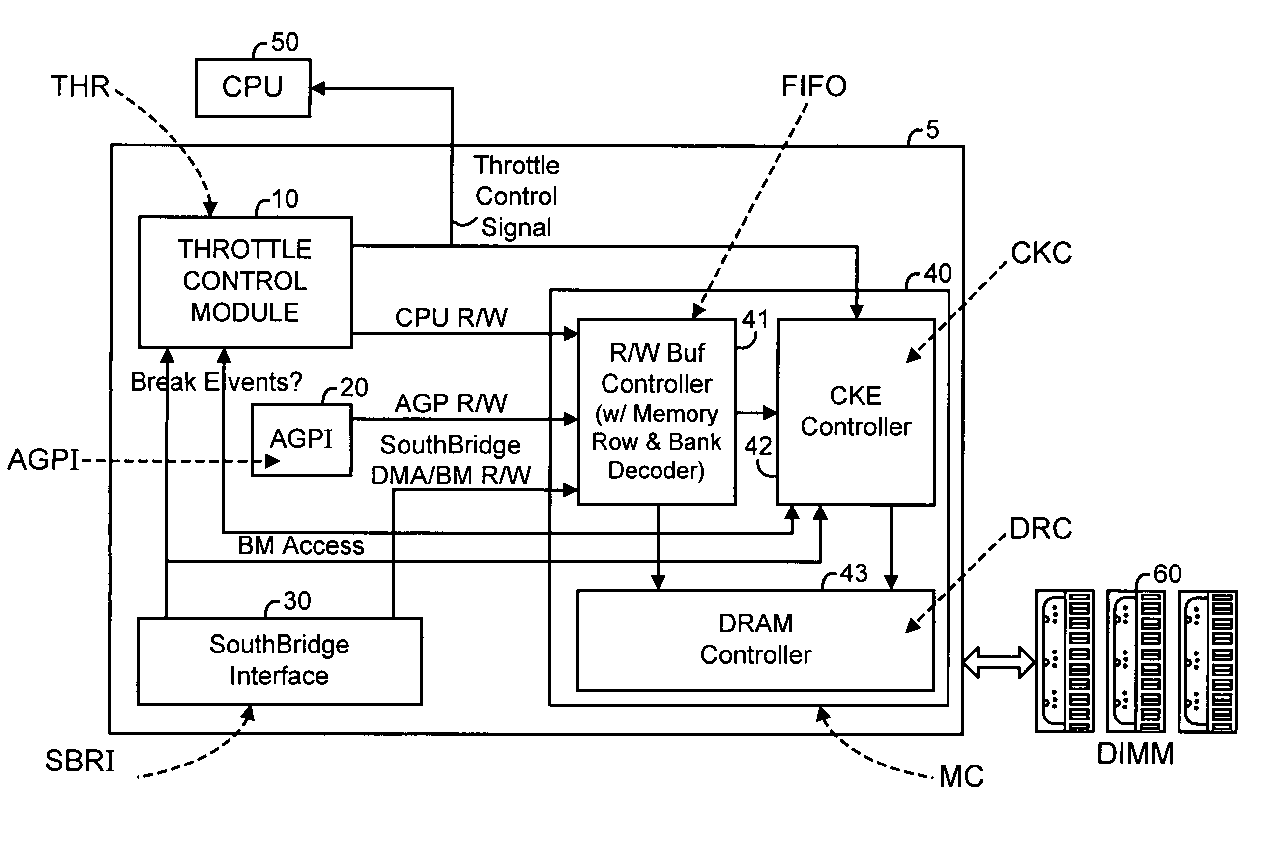
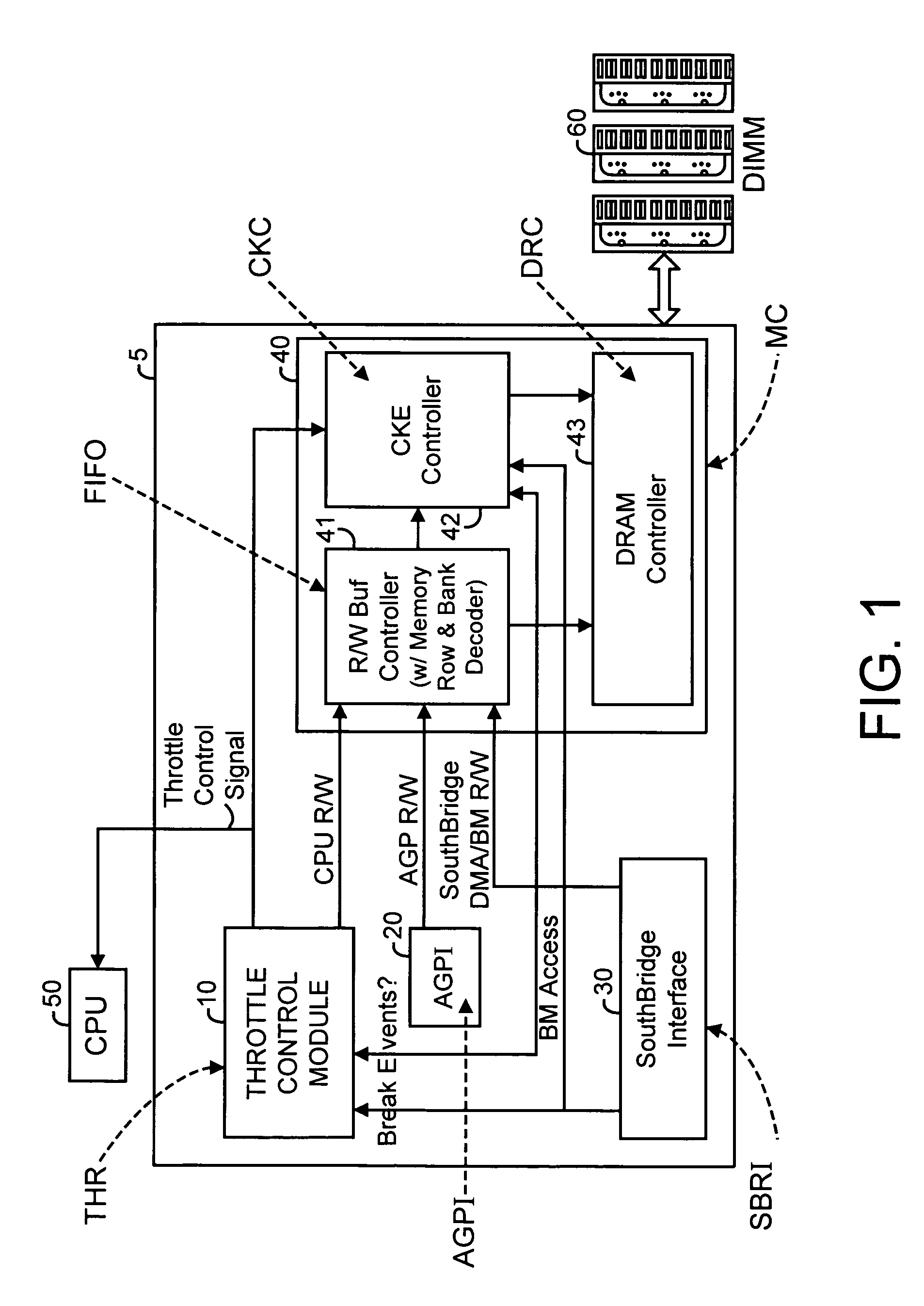
[0026]FIG. 1 is a schematic block diagram of a memory power management system 5 interfacing to a CPU 50 and a memory subsystem 60 in accordance with an embodiment of the present invention. Memory power management system 5 includes a CPU throttle control (THR) module 10, an accelerated graphics port interface (AGPI) module 20, a southbridge interface (SBRI) module 30, and a memory controller (MC) module 40.

[0027]Other embodiments of the present invention may not include an AGPI module or a southbridge module but may instead include other interfaces to interface to other subsystems.

[0028]In accordance with an embodiment of the present invention, the MC module 40 includes a read / write buffer controller (FIFO) module 41, a DRAM controller (DRC) module 43, and a DRAM clock enable controller (CKC) module 42.

[0029]The THR module 10 performs CPU profiling, collects statistics of CPU performance, and performs intelligent predictions to generate an adaptive CPU throttle control signal to cont...


PUM


Abstract

A method and apparatus are disclosed for performing adaptive memory power management in a system employing a CPU and a memory subsystem. A CPU throttle control (THR) module generates a CPU throttle control signal indicating when the CPU is idle. A memory controller (MC) module generates memory power management signals based on at least one of the CPU throttle control signal, memory read/write signals, memory access break events, and bus master access requests. Certain portions of the memory subsystem are powered down in response to the memory power management signals. Memory power management is performed on a time segment by time segment basis to achieve efficient power management of the memory subsystem during CPU run time.

Description

RELATED APPLICATIONS[0001]The present application claims priority to and the benefit of application Ser. No. 10 / 146,554, filed on May 15, 2002, and incorporates said application herein by reference in its entirety.BACKGROUND OF THE INVENTION[0002]Advanced CPU's and embedded processors are achieving higher performance as time goes on. However, memory subsystems are requiring lower latency and more bandwidth to sustain performance. Dynamic random access memory (DRAM), for example, is getting faster in clock speed, wider in bus size, and larger in capacity. As a result, DRAM is consuming more power and generating more heat. The wider bus effectively increases the memory subsystem power consumption linearly, whether it is for embedded appliances, Desktop / Notebook PC's, or high-density Server applications.[0003]A CPU is the computing and control hardware element of a computer-based system. In a personal computer, for example, the CPU is usually an integrated part of a single, extremely p...

Claims


Application Information

Patent Timeline
Patent Type & Authority Patents(United States)
IPC IPC(8): G06F1/32
CPCG06F1/3203G06F1/3225G06F1/3275Y02B60/1228Y02B60/1225Y02B60/32Y02D10/00Y02D30/50
Inventor MA, KENNETH
Owner AVAGO TECH INT SALES PTE LTD
Why Eureka
Try Eureka