Method and apparatus for identifying problems in computer networks

a computer network and problem technology, applied in the field of computer networks, can solve problems such as inefficient traditional approach on several levels, complex topological representations of large networks, and often problematic integration requiring extensive manipulation and correlation

Inactive Publication Date: 2006-04-11
OPTANIX INC
View PDF19 Cites 312 Cited by
  • Summary
  • Abstract
  • Description
  • Claims
  • Application Information

AI Technical Summary

Benefits of technology

[0009]The invention discloses a network management appliance and methods for identifying, diagnosing, and documenting problems in computer networks using the appliance. The devices and process available on a network, as well as grouping of the same, are collectively referred to hereafter as “objects”. Accordingly, a monitored or managed object may be physical device(s), process(es) or logical associations or the ...

Problems solved by technology

Integration is often problematic requiring extensive manipulation and correlation of alarm conditions prior to problem and problem resolution documentation.
Such a traditional approach is inefficient on several levels.
Topological representations of large networks are also problematic.
Further, adequate documentation and description of a problem or fault conditions and its corresponding resolution is essential but difficult to ach...

Method used


Image

  • Method and apparatus for identifying problems in computer networks
  • Method and apparatus for identifying problems in computer networks
  • Method and apparatus for identifying problems in computer networks

Examples


Embodiment Construction

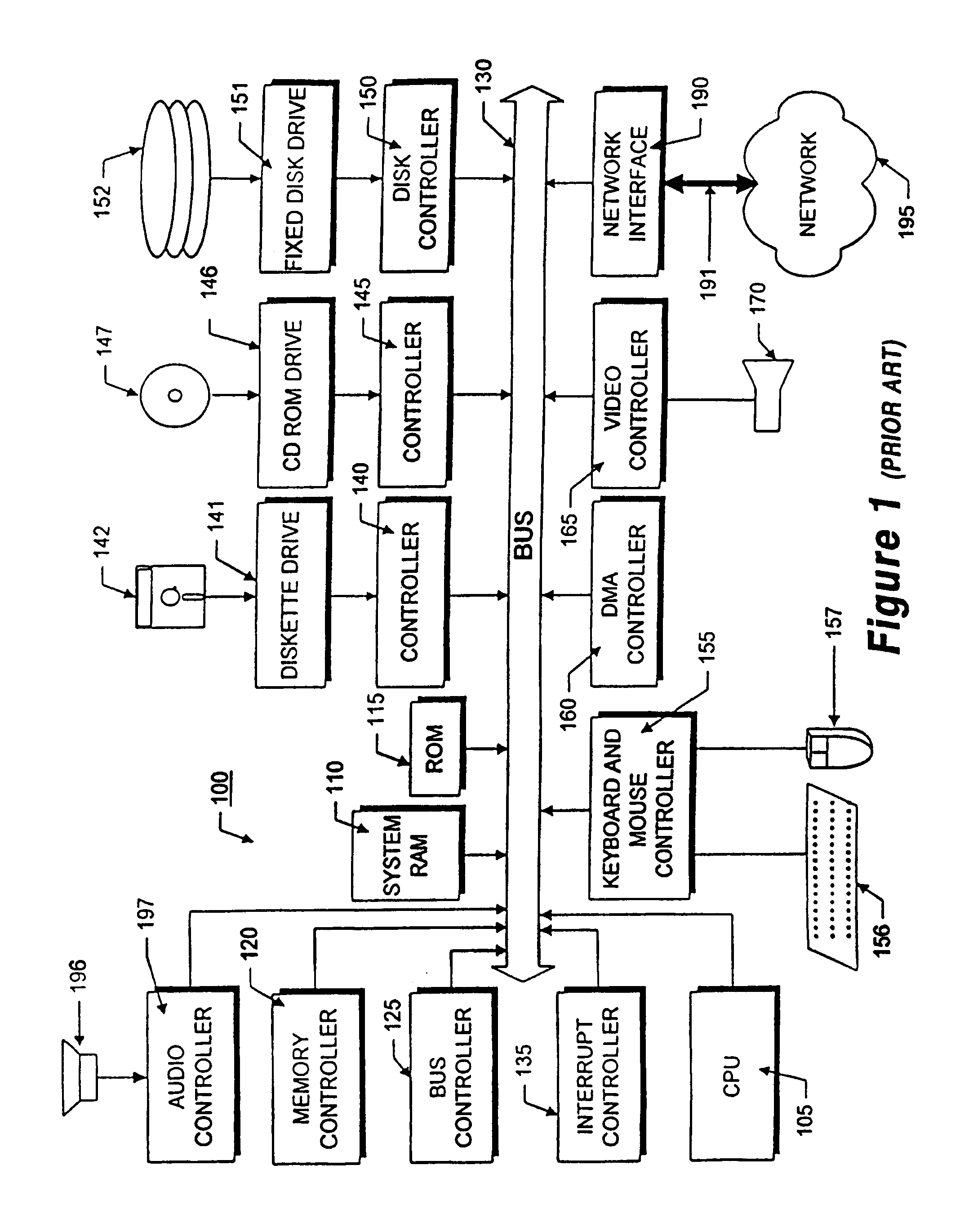
[0035]FIG. 1 illustrates the system architecture for a computer system 100, such as a Dell Dimension 8200, commercially available from Dell Computer, Dallas Tex., on which the invention can be implemented. The exemplary computer system of FIG. 1 is for descriptive purposes only. Although the description below may refer to terms commonly used in describing particular computer systems, the description and concepts equally apply to other systems, including systems having architectures dissimilar to FIG. 1.

[0036]The computer system 100 includes a central processing unit (CPU) 105, which may include a conventional microprocessor, a random access memory (RAM) 110 for temporary storage of information, and a read only memory (ROM) 115 for permanent storage of information. A memory controller 120 is provided for controlling system RAM 110. A bus controller 125 is provided for controlling bus 130, and an interrupt controller 135 is used for receiving and processing various interrupt signals f...


PUM


Abstract

A network appliance for monitoring, diagnosing and documenting problems among a plurality of devices and processes (objects) coupled to a computer network utilizes periodic polling and collection of object-generated trap data to monitor the status of objects on the computer network. The status of a multitude of objects is maintained in memory utilizing virtual state machines which contain a small amount of persistent data but which are modeled after one of a plurality of finite state machines. The memory further maintains dependency data related to each object which identifies parent/child relationships with other objects at the same or different layers of the OSI network protocol model. A decision engine verifies through on-demand polling that a device is down. A root cause analysis module utilizes status and dependency data to locate the highest object in the parent/child relationship tree that is affected to determine the root cause of a problem. Once a problem has been verified, a “case” is opened and notification alerts may be sent out to one or more devices. A user interface allows all objects within the network to be displayed with their respective status and their respective parent/child dependency objects in various formats.

Description

FIELD OF THE INVENTION[0001]This invention relates generally to computer networks and more specifically, to an apparatus and methods for identifying, diagnosing, and documenting problems in computer networks including networking devices, servers, appliances, and network services collectively known as objects.BACKGROUND OF THE INVENTION[0002]Much prior art has focused on identifying network and / or system fault conditions. Additionally, prior art has used topological network maps and diagnostic tools to display network fault conditions. Such tools have been designed to allow less skilled network administrators to conduct support from a network or system management station. Occasionally, network and / or system management systems interface with an exterior system for the documentation of problems and resolutions. Integration is often problematic requiring extensive manipulation and correlation of alarm conditions prior to problem and problem resolution documentation.[0003]Such a traditio...

Claims


Application Information

Patent Timeline
IPC IPC(8): G06F11/00
CPCG06F11/3495H04L43/10H04L43/0817
Inventor LOVY, DAVID M.FAGAN, BRANT M.BOJANEK, ROBERT J.
Owner OPTANIX INC
Why Eureka
Try Eureka