Condenser for refrigerating machine

a technology for refrigerating machines and condensers, which is applied in the direction of refrigeration components, indirect heat exchangers, lighting and heating apparatus, etc., can solve the problems of increasing the heat resistance of tubes and degradation of the condensation performance of the condenser, and achieve the effect of improving the condensation performan

Inactive Publication Date: 2006-04-18
MITSUBISHI HEAVY IND LTD
View PDF26 Cites 7 Cited by
  • Summary
  • Abstract
  • Description
  • Claims
  • Application Information

AI Technical Summary

Benefits of technology

[0009]The present invention has an object of suppressing accumulation or concentration of the condensed liquid around the heat exchanger tubes and to provide a condenser for the refrigerating machine having improved condensation performance.
[0010]The present invention provides a condenser for a refrigerating machine which comprises a vessel into which a gaseous refrigerant is introduced and a bundle of heat exchanger tubes disposed in said vessel for condensing and liquefying a gaseous refrigerant by heat exchange between said gaseous refrigerant and cooling water circulating in the heat exchanger tubes, wherein one or a plurality of vacant spaces are formed with a vertical orientation in the area in which the heat exchanger tubes are disposed, in order to prevent the liquefied refrigerant from accumulating around the second group of heat exchanger tubes and to accelerate the inflow of the gaseous refrigerant.

Problems solved by technology

However, a problem arises in that, since the heat exchanger tubes are arranged densely in the above-described condenser, the condensed liquid refrigerant moves towards the right and left sides of the vessel along the heat exchanger tubes by the supply pressure of the gaseous refrigerant introduced into the vessel and the condensed liquid often accumulates in both the right and left end portions of the foreward side heat exchanger tubes located lower in of the vessel.
When the condensed liquid is accumulated around the second group of heat exchanger tubes, the thick condensed liquid layer accumulated around the heat exchanger tubes causes an increase in the heat resistance of the tubes and causes degradation of the condensation performance of the condenser.

Method used


Image

  • Condenser for refrigerating machine
  • Condenser for refrigerating machine
  • Condenser for refrigerating machine

Examples


Embodiment Construction

[0023]Hereinafter, embodiments of the condensers for the refrigerating machine of the present invention will be described.

[0024]FIG. 1 shows a schematic structure of a refrigerating machine. This refrigerating machine comprises a condenser 10 for condensing and liquefying a refrigerant by heat exchange between the cooling water and gaseous refrigerant, an expansion valve 11 for pressure reduction of the condensed refrigerant, an evaporator 12 for cooling the cooling water by heat exchange between the condensed refrigerant and the cooling water, and a compressor 13 for supplying the refrigerant to the condenser 10 after evaporation and vaporization of the refrigerant. Note that the cooled water in the above-described evaporator is used for cooling of the building.

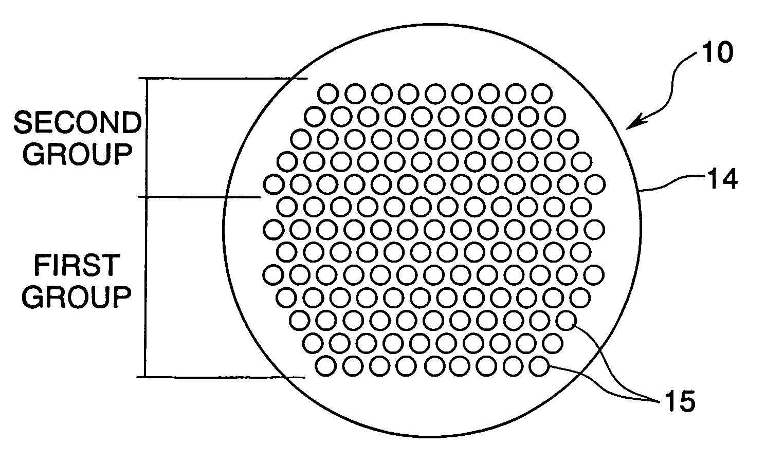
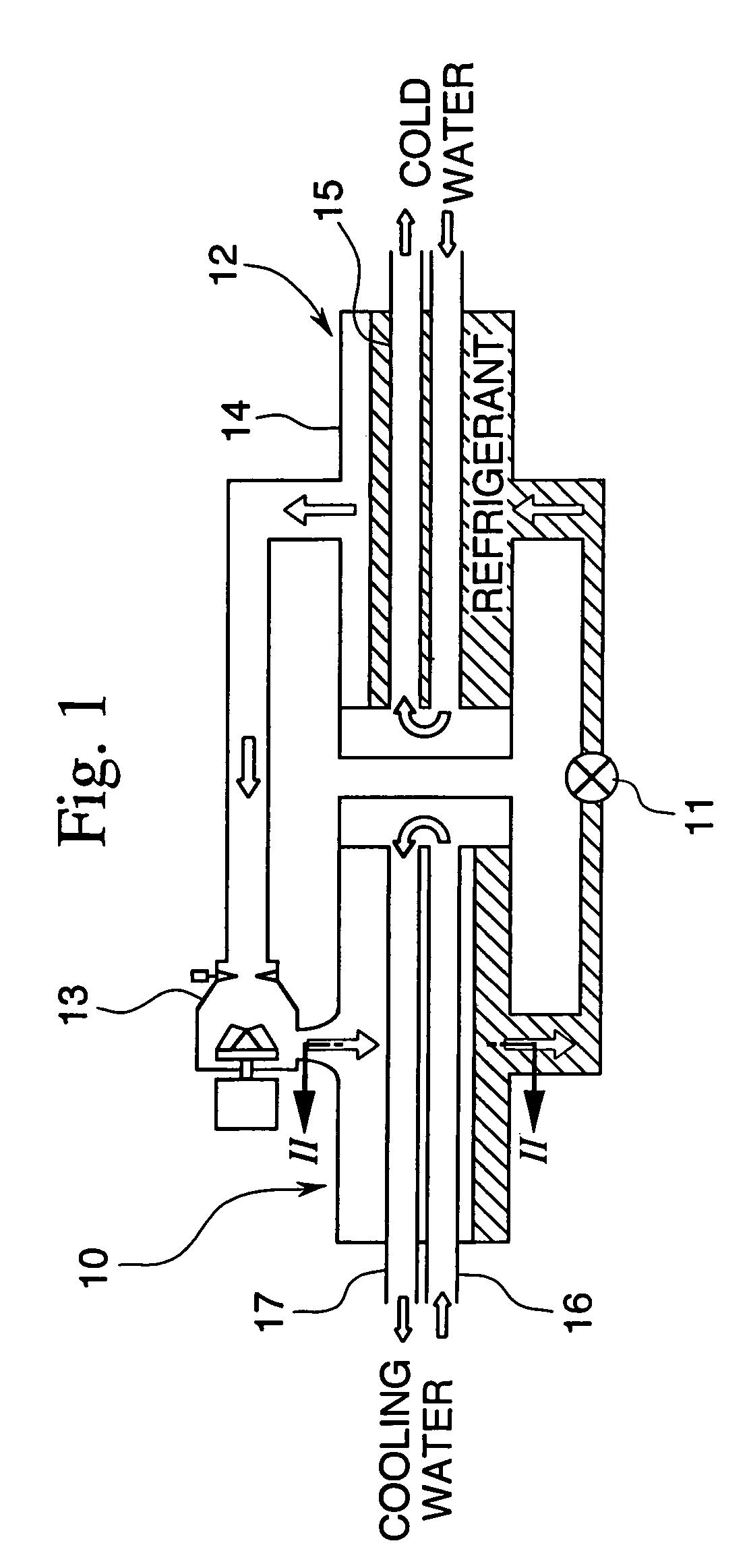
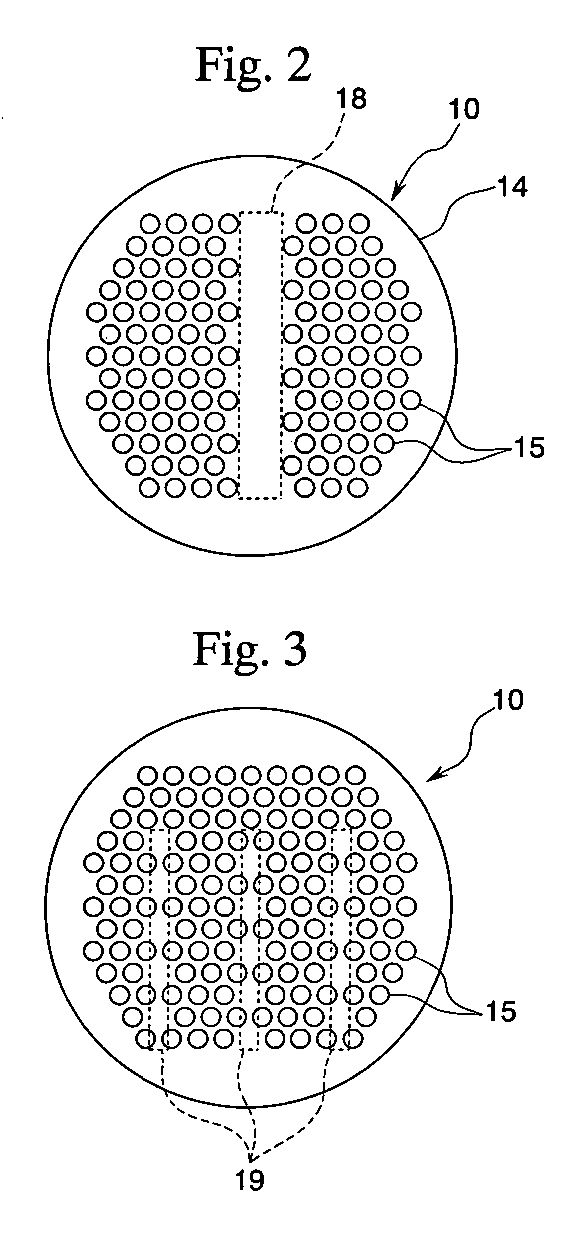
[0025]FIG. 2 is a cross-sectional view along the line II—II in FIG. 1. A shown in FIG. 2, the condenser comprises a cylindrical vessel 14 and a plurality of heat exchanger tubes 15 which are arranged as a bundle in the vesse...


PUM


Abstract

This invention provides a condenser for a refrigerating machine which can improve the condensation characteristics by eliminating the accumulation of the condensed refrigerant in the condenser vessel. The condenser comprising the vessel 14 and a group of heat exchanger tubes 15 disposed in the vessel is used for condensing and liquefying the gaseous refrigerant by heat exchange between the gaseous refrigerant and cooling water circulating in the heat exchanger tubes. The condenser is constituted such that accumulated liquefied refrigerant is removed by forming one or a plurality of spaces in the area wherein the heat exchanger tubes are disposed.

Description

[0001]This application is a division of U.S. patent application Ser. No. 09 / 983,159 filed Oct. 23, 2001 now abandoned, the entire contents of which are incorporated herein by reference.BACKGROUND OF THE INVENTION[0002]1. Field of the Invention[0003]The present invention relates to a condenser for a refrigerating machine, which is used for condensing and liquefying a gaseous refrigerant after heat exchange between the gaseous refrigerant and cooling water.[0004]2. Description of the Related Art[0005]In a large scale structure such as a building, for example, the inside space of the building is cooled by circulating cooled water in pipes installed in the building for heat exchange between the cooled water and the air in the building.[0006]FIG. 7 shows an example of a condenser included in a refrigerating machine. As shown in FIG. 7, this condenser comprises a cylindrical vessel 1 in which a bundle of a plurality of heat exchanger tubes 2 is arranged in a staggered manner.[0007]There a...

Claims


Application Information

Patent Timeline
Patent Type & Authority Patents(United States)
IPC IPC(8): F28B1/00F28F13/06F25B39/04F28B1/02F28D7/16F28F13/08
CPCF25B39/04F28D7/1638F28B1/02F25B2339/0242F25B2339/047
Inventor IRITANI, YOICHIROKAWADA, AKIHIROSHIRAKATA, YOSHINORISEKI, WATARUHIROKAWA, KOJI
Owner MITSUBISHI HEAVY IND LTD
Why Eureka
Try Eureka