
Machine for mixing and distributing products used to feed livestock

Inactive Publication Date: 2006-04-18
LUCAS G
View PDF11 Cites 23 Cited by
  • Summary
  • Abstract
  • Description
  • Claims
  • Application Information

AI Technical Summary

Benefits of technology

[0012]The present invention provides a feeding mixing machine comprising means which enable efficient cutting of the product, such as hay or straw and in particular all types of hay.

Problems solved by technology

The product may indeed accumulate and there may be jams between both screws, when hay or straw bales are injected on the transfer screw.

Method used


Image

  • Machine for mixing and distributing products used to feed livestock
  • Machine for mixing and distributing products used to feed livestock
  • Machine for mixing and distributing products used to feed livestock

Examples


Embodiment Construction

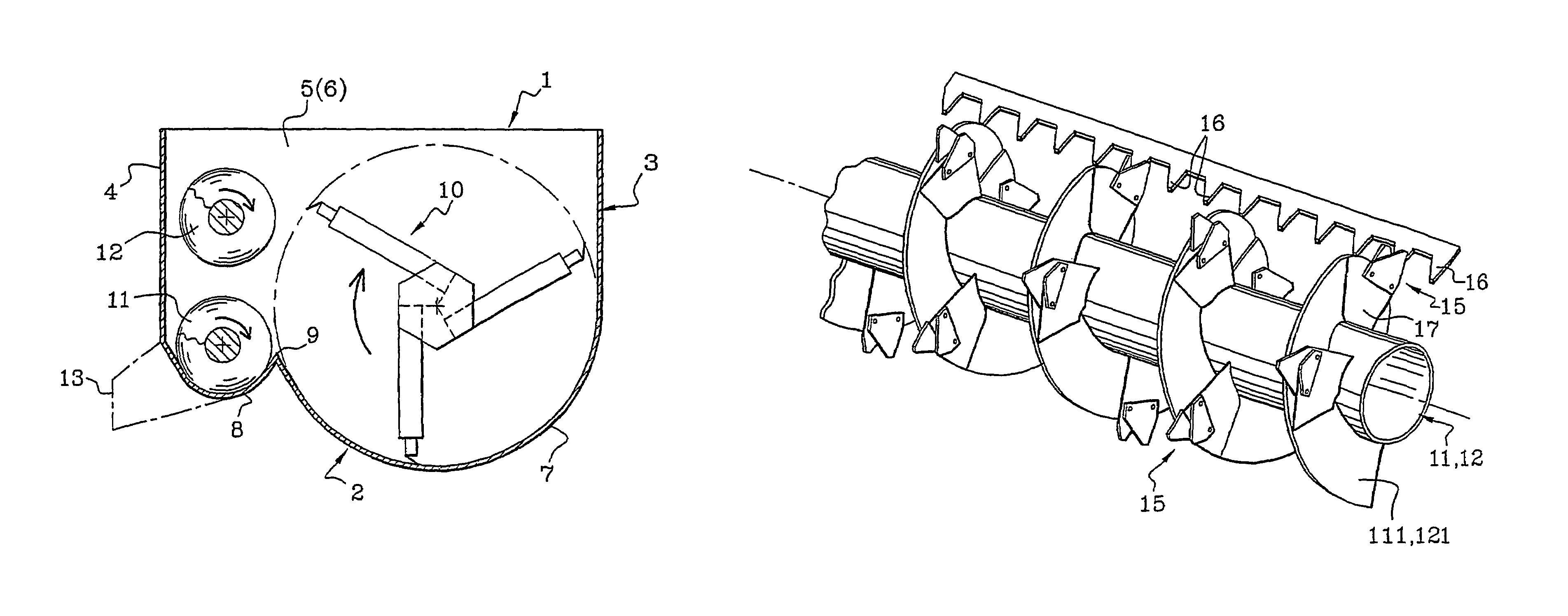
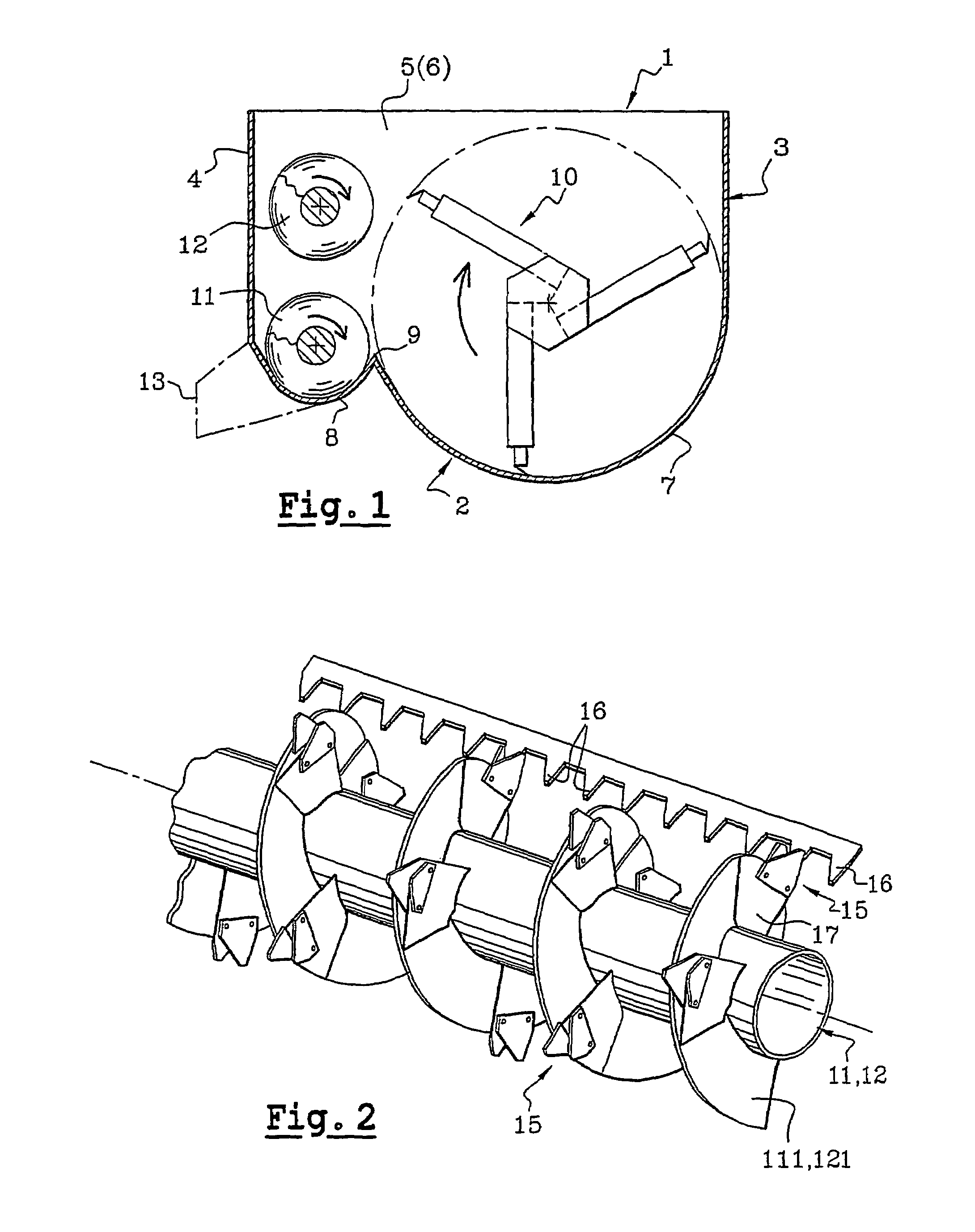
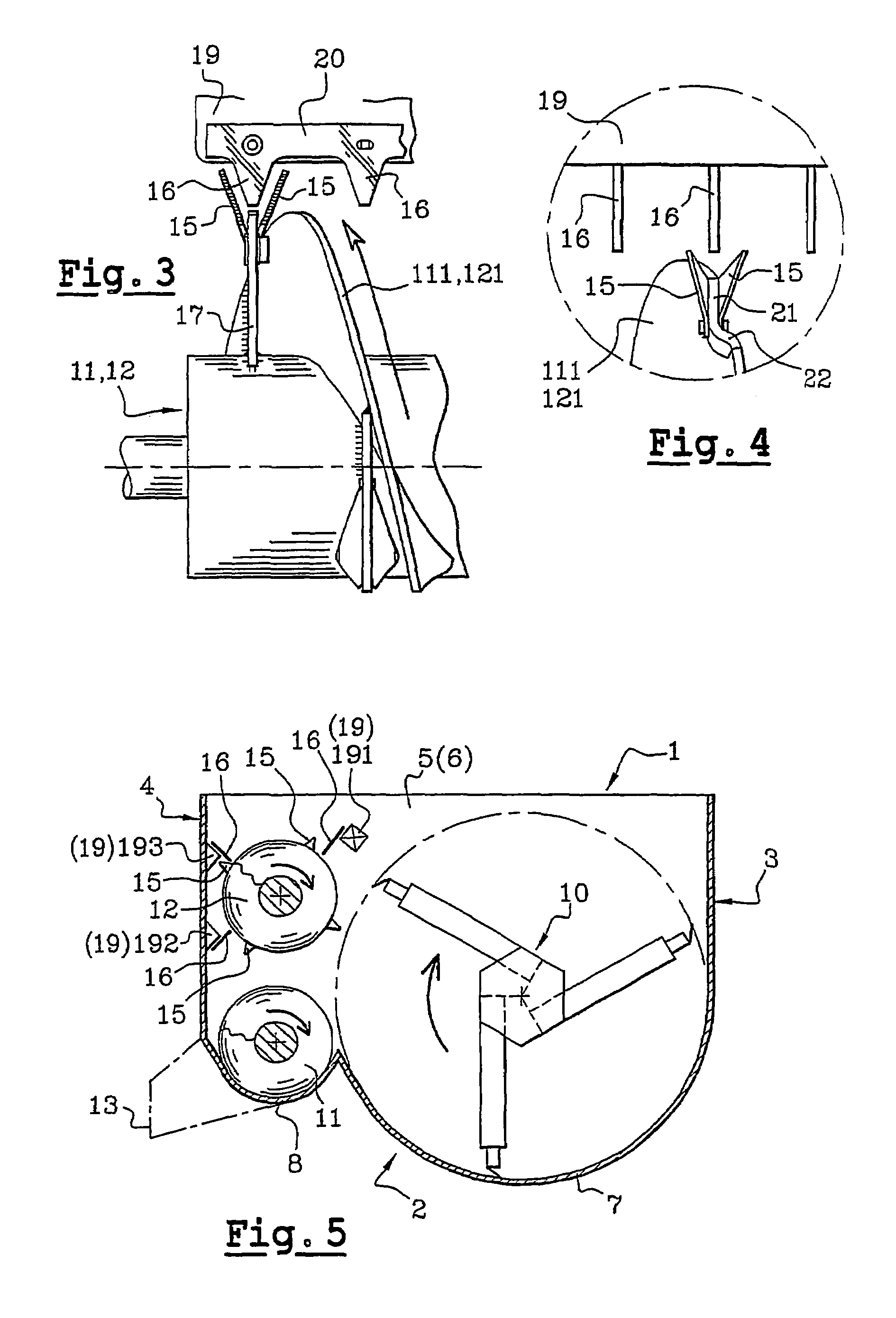
[0037]The feeding mixing machine is as that which is described in the document EP-498 543 mentioned above, and only the portions useful to the understanding of the invention are detailed hereunder.

[0038]This machine comprises a skip 1 in the form of a tank, open on the top, delineated by a bottom 2, lateral walls 3 and 4 and end walls 5 and 6 as represented on the different figures.

[0039]The bottom 2 comprises two portions 7 and 8 in the form of troughs of different radius. The radius of the portion 8 is of the order of three to four times smaller than that of the portion 7 and both these portions joining while forming a ridge 9.

[0040]The bottom 7 constitutes the partial casing of a mixing rotor 10 extending longitudinally between the end walls 5 and 6. The bottom 8 surrounds a screw 11 partially extending parallel to the mixing rotor 10. This screw 11 has a diameter which is three to four times smaller than that of the rotor 10 and its upper periphery lies substantially at the same...


PUM


Abstract

A machine including a container fitted with a base that extends between lateral walls and end walls. The base partially covers (i) a mixing rotor and (ii) a feed auger which moves products in the skip either in a closed circuit or in a circuit towards a distributing chute. A transfer screw is mounted on top of the feed auger. The transfer screw can include cutting members in the form of sectioning parts. The sectioning parts co-operate with teeth which are disposed on a beam. The teeth can be positioned as necessary either on a beam located in the container or on one or more beams located on the lateral wall. Similarly, the feed auger can also include sectioning parts that co-operate with teeth if required.

Description

BACKGROUND OF THE INVENTION[0001]This present invention relates to a mixing machine for distribution of product for feeding cattle.DESCRIPTION OF THE RELATED ART[0002]This type of machine, described particularly in document U.S. Pat. No. 3,672,640, consists of a skip open on the top; this skip comprises a rotor with large diameter extending longitudinally between the end walls and which is partially surrounded by a rounded bottom in the form of a trough. This rotor stirs and mixes the product which it propels gradually towards an endless screw arranged laterally, parallel to said rotor and whereof the diameter is three to four times smaller than that of the latter.[0003]This lateral screw also extends between both end walls and it is also surrounded partially by a bottom in the form of a trough; it moves continuously and longitudinally the product from one end to the other of the skip toward the end thereof where lies the feeding orifice so that, when this orifice is closed by an ap...

Claims


Application Information

Patent Timeline
IPC IPC(8): B02C19/22A01K5/00B01F7/00B01F15/00
CPCA01K5/002B01F7/00008Y10S366/603Y10S241/605B01F27/05
Inventor LUCAS, GERARDRETAILLAUD, JEAN-CLAUDE
Owner LUCAS G
Learn More