Modified rumble strip cutter

a technology of rumble strips and cutters, which is applied in cutting machines, roads, construction, etc., can solve the problems of limited cutting speed of rumble strips

Inactive Publication Date: 2006-04-18
WIRTGEN AMERICA
View PDF134 Cites 11 Cited by
  • Summary
  • Abstract
  • Description
  • Claims
  • Application Information

AI Technical Summary

Benefits of technology

[0015]It is further a desirable objective for an efficient rumble strip cutter to be able to lift the cutter out of engagement with the road so that the machine can be driven at a relatively rapid rate of speed from one job site to another.
[0016]It is yet another desirable objective for a rumble strip cutter to have a machine in which the rumble strip cutting drum can be easily moved from one side of the machine to the other so that the rumble strip cutter can be driven in the direction of moving traffic on an interstate type highway regardless of which shoulder of the highway is being cut, while being able to cut close to obstructions and on narrow shoulders.
[0018]Another desirable feature for a rumble strip cutter is to have a device that will provide additional pressure to hold the rumble strip cutting drum in cutting engagement with the road surface as the machine is operated.
[0019]Another desirable objective for a rumble strip cutter is to have a machine on which the power supply belt can be adjusted to increase or decease the tension on the belt so as to maximize the efficiency of the drive train power system.
[0025]An improved rumble strip cutter for cutting rumble strips in a road surface including: a rumble strip cutter frame having opposing sides; a piston wheel for imparting up and down motion to a portion of said frame; a connector for connecting a portion of said frame to a tractor so that a portion of said frame can pivot in an up and down motion; a rumble strip cutting drum removably mounted on one side of said frame; lifting structure positioned between said connector and said drum for connection of said frame to a tractor enabling said rumble strip cutting frame to be lifted so that the cutting drum can be spaced from the road surface when the rumble strip cutter is being moved from one job site to another.
[0026]A rumble strip cutting machine including a frame having opposing side rails spaced from each other and an axle extending between said rails with a rumble strip cutting drum having a length of less than half the distance between the said rails and removably mounted on said axle adjacent one of said rails, the improvement including: a rumble strip motion wheel assembly including a piston wheel rotatably mounted in said assembly; said assembly pivotally mounted to said frame; and a connector between said assemble and said frame that can be adjusted in length so that said assembly can be pivoted to raise or lower said piston wheel in relationship to said rumble strip cutting drum in order to adjust the depth of cut of said cutting drum.

Problems solved by technology

Further, the speed at which rumble strips can be cut is limited because of the vibrations transferred from the cutting machine to the operator of the machine.

Method used


Image

  • Modified rumble strip cutter
  • Modified rumble strip cutter
  • Modified rumble strip cutter

Examples


Embodiment Construction

[0049]Referring now to the drawings, wherein like numbers refer to like parts throughout, a preferred embodiment of the machine and method constituting the present invention will be described. The description is, however, not to be considered a limitation of the invention as set forth in the claims appended hereto.

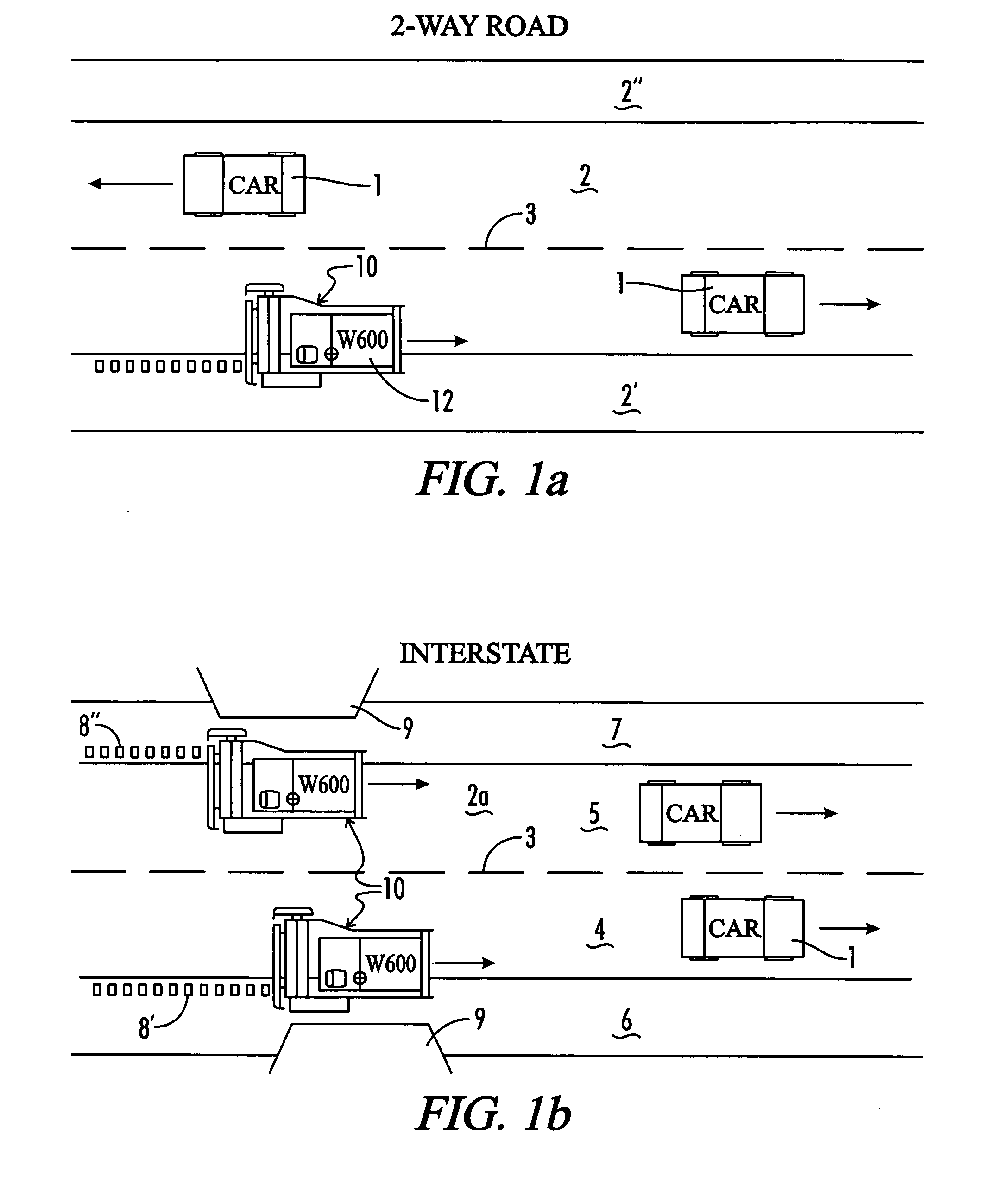
[0050]The environment in which the present invention operates is illustrated in FIGS. 1a and 1b. In FIG. 1a, a two-lane highway is shown with cars moving in opposite directions over a highway 2 on either side of a centerline 3. Outside the margins of the highway 2 are shoulders 2′ and 2″ on the right and left sides of the road respectively. In FIG. 1a, the rumble strip cutter 10 is shown on the right side of the road moving in the direction of travel of the car in the right hand lane. The rumble strip cutter 10 is mounted to a self-propelled vehicle 12 for driving the rumble strip cutting machine along the shoulder 2′ of the highway 2. The self propelled machine 10 can be ...


PUM


Abstract

A rumble strip cutting machine having a drum that can be shifted from one side of the machine to the other. The machine includes a piston wheel that imparts an up and down motion to the frame so that rumble strips can be cut at desired intervals as the machine is driven along the road shoulder. The piston wheel includes a wheel mounting assembly on each side of the machine so that the wheel can be conveniently shifted from one side of the machine to the other. Additional structures allow for the flexing of the machine frame, applying pressure to the cutting drum, adjusting the depth of cut, tightening the belt used to drive the drum, and lifting the machine for job site transportation. The machine enables a method of cutting rumble strips close to obstructions on narrow shoulders while driving the machine in the direction of moving traffic.

Description

[0001]This application is a Non-Provisional application, which claims benefit of co-pending U.S. Provisional Patent Application Ser. No. 60 / 363,137 filed Mar. 11, 2002, entitled “Modified Rumble Strip Cutter” which is hereby incorporated by reference.[0002]A portion of the disclosure of this patent document contains material that is subject to copyright protection. The copyright owner has no objection to the facsimile reproduction by anyone of the patent document or the patent disclosure, as it appears in the Patent and Trademark office patent file or records, but otherwise reserves all copyright rights whatsoever.[0003]Be it known that we, Stuart W. Murray, a citizen of the United States, residing at 9412 Ashford Place, Brentwood, Tenn. 37027; Scott F. Lyons, a citizen of the United States, residing at 5717 Cedar Ash Crossing, Nashville, Tenn. 37013; have invented a new and useful “Modified Rumble Strip Cutter.”BACKGROUND OF THE INVENTION[0004]The present invention relates generall...

Claims


Application Information

Patent Timeline
Patent Type & Authority Patents(United States)
IPC IPC(8): E01C23/09
CPCE01C23/0993E01C2301/50
Inventor MURRAY, STUART W.LYONS, SCOTT
Owner WIRTGEN AMERICA
Why Eureka
Try Eureka