Contact lens and contact lens design method

a technology of contact lens and design method, which is applied in the field of contact lens, can solve the problems of not being able to provide optimal correction of vision of lens wearers, unable to ignore, and insufficiently focusing on optical characteristics on the optical axis of contact lens design, etc., and achieves easy and satisfactory co-operation. , the effect of optimal vision

Inactive Publication Date: 2006-04-18
MENICON CO LTD
View PDF18 Cites 7 Cited by
  • Summary
  • Abstract
  • Description
  • Claims
  • Application Information

AI Technical Summary

Benefits of technology

[0012]It is therefore one object of this invention to provide a contact lens of novel structure that is capable of ensuring an excellent wear comfort through a lens back surface of aspheric shape designed considering a shape of a cornea, and that is also capable of exhibiting excellent optical characteristics even when the pupil centerline is decentered with respect to the lens optical axis, thereby ensuring consistently good vision.

Problems solved by technology

However, a contact lens is worn on a cornea of an eye, and it is therefore no longer possible to ignore factors such as the optical system of the eye per se, the lens effect resulting from a tear fluid layer formed between the contact lens and the cornea during wear (tear-fluid lens effect) and the like.
In this respect, an extensive research conducted by the inventors, as well as numerous clinical trials and studies based thereon have revealed that the presumption in lens design that emphasizes optical characteristics on the optical axis of the contact lens is in itself highly problematic, and that contact lenses deemed optimal under conventional contact lens design methods may practically fail to provide optimal correction of vision of lens wearers.
Therefore, corneal corrective surgery performed with the object of eliminating image aberration on the pupil centerline, for example, may possibly causes aberration further away from the pupil centerline, which conversely increases due to lack of aberration on the pupil centerline, resulting in adverse effects such as poor vision and headache.
Accordingly, where contact lenses typically come to rest at positions with the lens optical axes offset from the pupil centerlines as described above, lenses that have been designed optimally according to conventional lens design methods tend to produce problems such as significantly impaired vision in the course of actual wear.

Method used


Image

  • Contact lens and contact lens design method
  • Contact lens and contact lens design method
  • Contact lens and contact lens design method

Examples


example

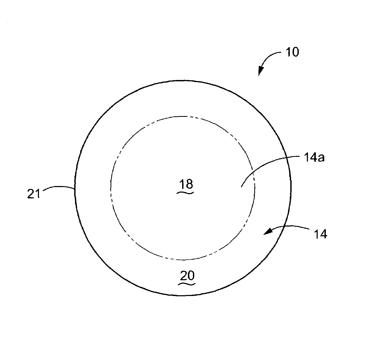
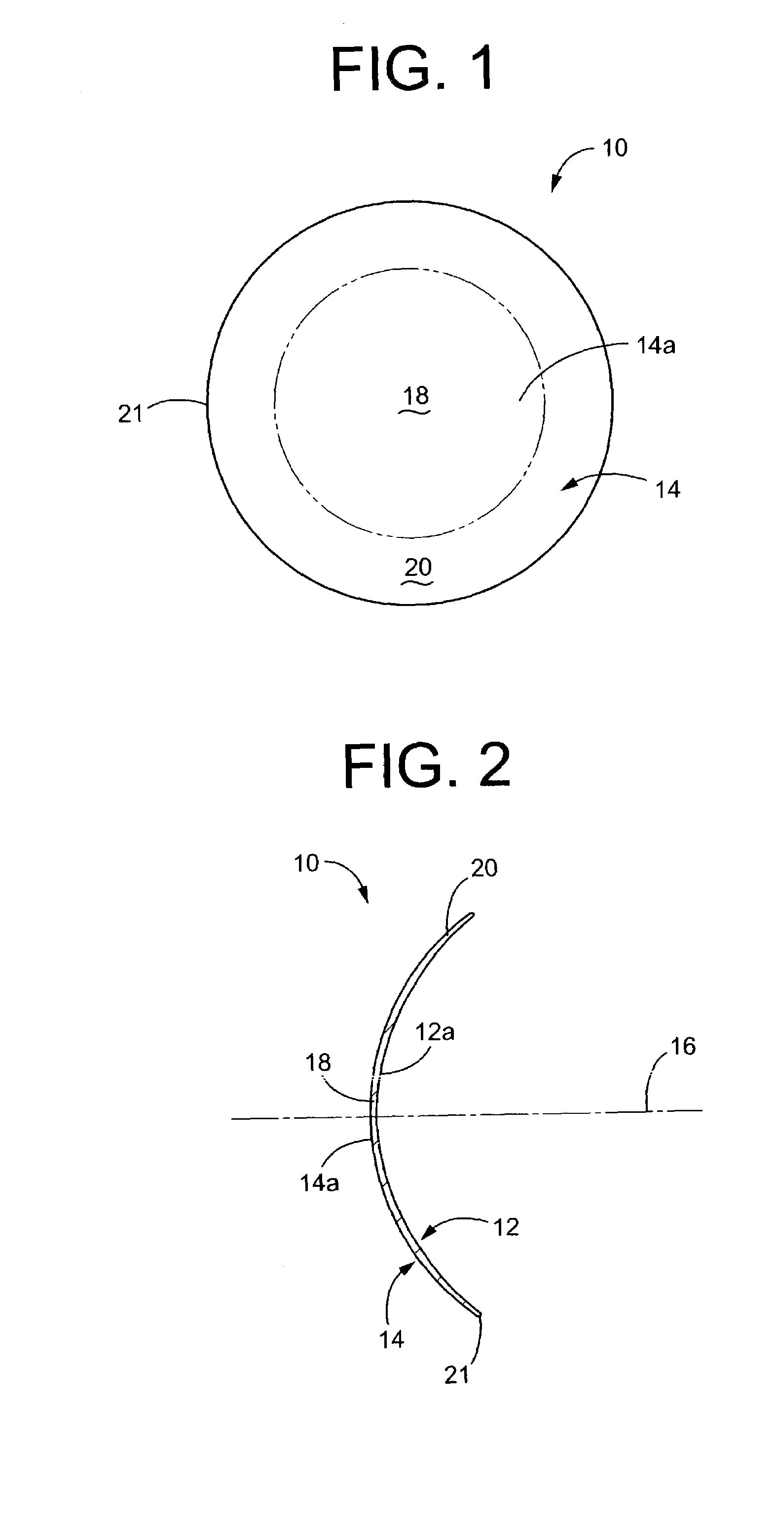
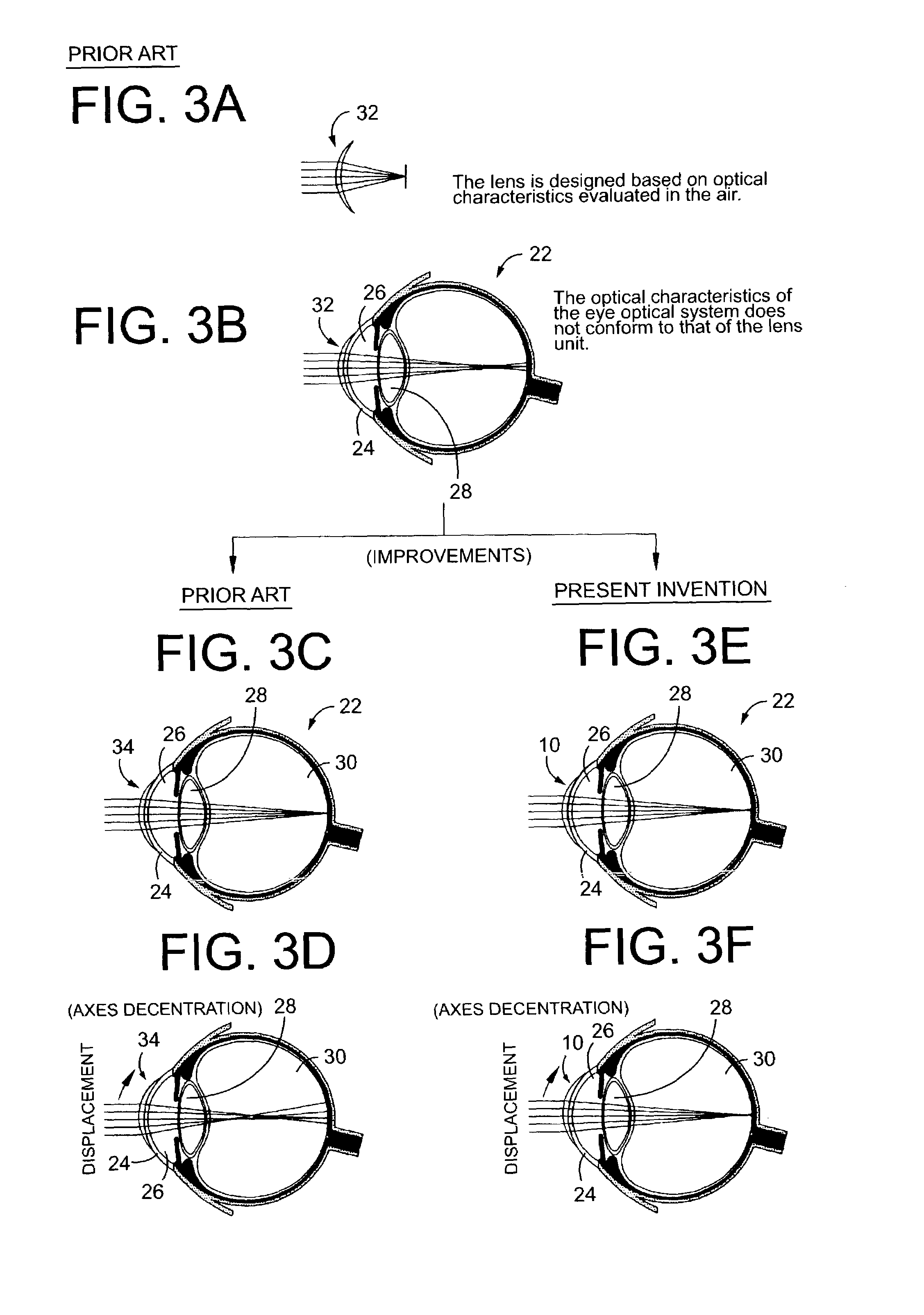
[0062]For hard contact lenses of gas permeable polymethyl methacrylate (PMMA), optical simulations were used to arrive at conic coefficients for the front optical zone 14a that would afford optimal optical characteristics under conditions of wear producing predetermined decentration, assuming the back optical zone 12a to be a spherical convex surface consisting of a spherical surface with a conic coefficient Ka of −0.1225. The simulations in this example were run setting the back optical zone 12a vertex radius of curvature ra to ra=6.0 mm and r=9.0 mm. For lens decentration during wear, optical simulations were run on the assumption that the intersect angle φ of the lens optical axis and pupil centerline was φ=0°, 5° and 10°, determining in each case conic coefficient Kb of the front optical zone 14a, which provides the best optical system.

[0063]For the optical simulations, the Gullstrand model of the eye was used as the optical system of the eye for hypothesizing physical shape, us...


PUM


Abstract

Disclosed is a contact lens having a refractive power ranging from −15.0 to +15.0 diopters in an optical zone thereof, wherein a back optical zone is a conical surface having a conic coefficient ranting from −0.04 to −0.49, and a front optical zone is a conical surface having a conic coefficient ranging from −0.02 to −0.50. The contact lens exhibits optical characteristics required in consideration of an optical system of an eye when being positioned at a position of rest during wear in which an optical axis of the optical zone is decentered with respect to an optical axis of the eye.

Description

INCORPORATED BY REFERENCE[0001]The disclosure of Japanese Patent Application No. 2002-013747 filed on Jan. 23, 2002 including the specification, drawings and abstract is incorporated herein by reference in its entirety.BACKGROUND OF THE INVENTION[0002]1. Field of the Invention[0003]The present invention relates generally to contact lenses, more particularly to a contact lens of novel structure which during wear on a cornea of an eye is capable of minimizing noticeable change upon decentering of an optical axis of an optical zone of the contact lens with respect to an optical axis of the eye, and to techniques related to such a contact lens.[0004]2. Description of the Related Art[0005]Conventionally, soft contact lenses and hard contact lenses (hereinafter referred to collectively as “contact lenses”) such as those disclosed in Japanese Patent Nos. 2,859,092 and 2,913,191, were generally designed with only a lens unit taken into consideration, like in optical lenses for use in other ...

Claims


Application Information

Patent Timeline
Patent Type & Authority Patents(United States)
IPC IPC(8): G02C7/04
CPCG02C7/028G02C7/04G02C2202/08G02C2202/04
Inventor SUZAKI, ASAKIKOBAYASHI, ATSUSHI
Owner MENICON CO LTD
Why Eureka
Try Eureka