
Method of gas carburizing

a gas carburizing and carburizing technology, applied in the direction of solid-state diffusion coating, metallic material coating process, coating, etc., can solve the problems of long time required, difficult to shorten the carburizing time below the time required for the surface carbon concentration the melting of the treatment object, etc., to achieve short time, increase the carburizing depth, and reduce the carburizing time

Active Publication Date: 2006-04-18
KOYO THERMO SYST CO LTD
View PDF8 Cites 0 Cited by
  • Summary
  • Abstract
  • Description
  • Claims
  • Application Information

AI Technical Summary

Benefits of technology

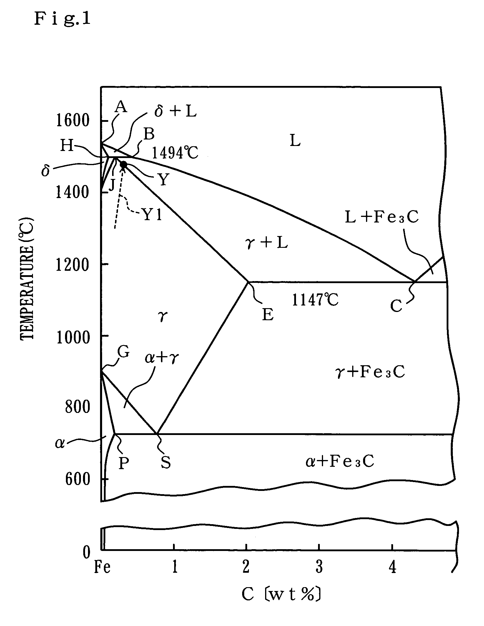
[0006]When the carburizing temperature and carburizing gas concentration are constant, long time is required for the carburized depth to reach its target value if the carburizing temperature is low, whereas if the carburizing temperature rises excessively, the surface carbon concentration of the treatment object exceeds a solid solubility limit before the carburized depth reaches its target value, and as a result the treatment object melts. Hence when the carburizing temperature land carburizing gas concentration are constant, it is difficult to shorten the carburizing time below the time required for the surface carbon concentration of the treatment object to reach a solid solubility limit (for example, to reach the JE line in FIG. 1). In response to this problem, the present invention achieves a reduction in the time required for carburizing processing by means of a novel relationship between the carburizing temperature, the carburizing time, and the surface carbon concentration of the treatment object.
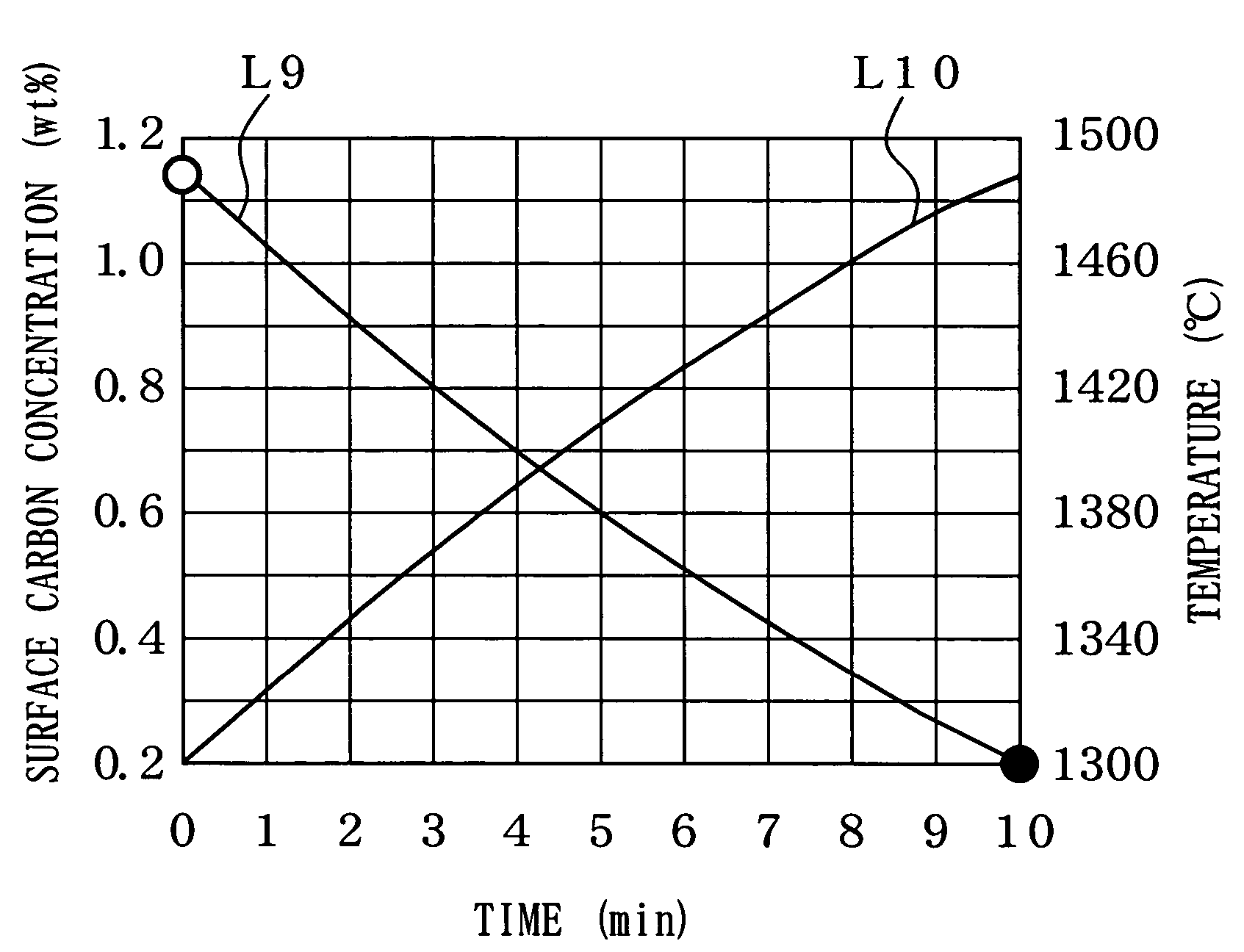
[0007]A method of gas carburizing according to the present invention is characterized in that it comprises a first process in which a steel treatment object in a carburizing atmosphere containing carburizing gas is heated to an initial set temperature which is not higher than a peritectic point at which δ iron and a liquid phase transform into γ iron and not less than a eutectic point at which the liquid phase transforms into γ iron and cementite, such that the surface carbon concentration of the treatment object does not exceed a solid solubility limit, and a second process following the first process in which the carburizing temperature is gradually decreased from the initial set temperature such that the surface carbon concentration of the treatment object increases without exceeding the solid solubility limit, and the carburized depth of the treatment object increases. According to the present invention, in the first process the surface carbon concentration of the treatment object can be increased to the vicinity of the solid solubility limit in a short amount of time, and in the second process the surface carbon concentration of the treatment object can be increased without melting the treatment object and also the carburized depth can be increased in a short amount of time.

Problems solved by technology

When the carburizing temperature and carburizing gas concentration are constant, long time is required for the carburized depth to reach its target value if the carburizing temperature is low, whereas if the carburizing temperature rises excessively, the surface carbon concentration of the treatment object exceeds a solid solubility limit before the carburized depth reaches its target value, and as a result the treatment object melts.
Hence when the carburizing temperature land carburizing gas concentration are constant, it is difficult to shorten the carburizing time below the time required for the surface carbon concentration of the treatment object to reach a solid solubility limit (for example, to reach the JE line in FIG. 1).

Method used


Image

  • Method of gas carburizing
  • Method of gas carburizing
  • Method of gas carburizing

Examples


Embodiment Construction

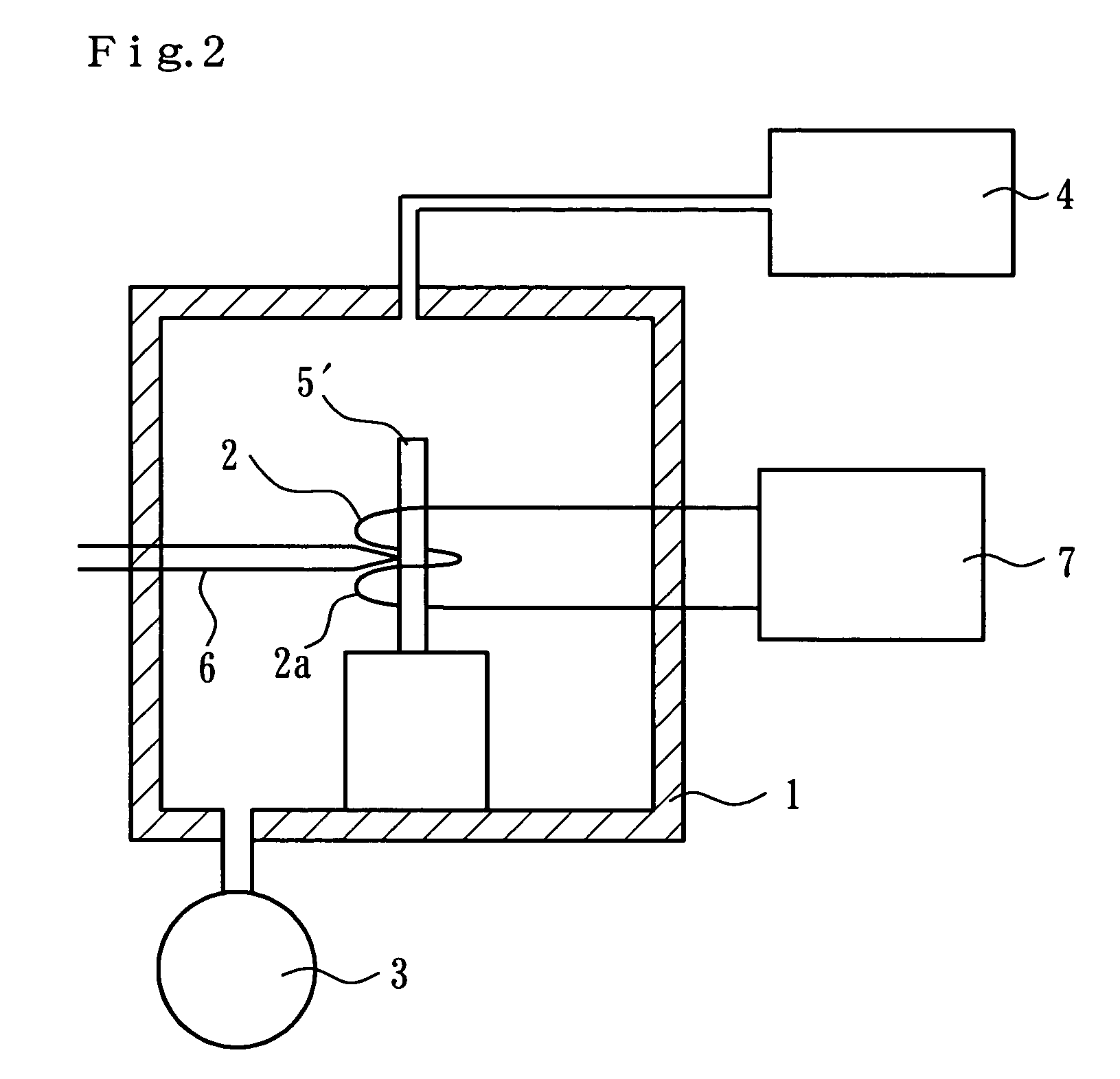
[0022]FIG. 2 shows a gas carburizing apparatus used in an embodiment of the present invention. The gas carburizing apparatus comprises a vacuum container 1, a heating device 2, a vacuum pump 3 for reducing the pressure inside the vacuum container 1, and a gas source 4 for supplying gas for carburizing atmosphere into the vacuum container 1. In this embodiment, the heating device 2 performs induction heating inside the vacuum container 1 using a coil 2a connected to a power source 7. The output from the power source 7 to the coil 2a is variable.

[0023]Prior to gas carburizing of a steel treatment object, a sample 5′ of the steel treatment object is gas carburized. In order to perform this gas carburizing, a thermocouple 6 is welded to the surface of the sample 5′ set to the heating device 2 as a sensor for detecting temperature. The temperature detection means are not limited to a thermocouple. Then, the pressure inside the vacuum container 1 is reduced by evacuating the vacuum contai...


PUM

PropertyMeasurementUnit
temperatureaaaaaaaaaa
pressureaaaaaaaaaa
pressureaaaaaaaaaa

Abstract

In a first process of a method of gas carburizing, a steel treatment object in a carburizing atmosphere containing carburizing gas is heated to an initial set temperature which is not higher than a peritectic point at which δ iron and a liquid phase transform into γ iron and not less than a eutectic point at which the liquid phase transforms into γ iron and cementite, such that the surface carbon concentration thereof does not exceed a solid solubility limit. In a second process following the first process, the carburizing temperature is gradually decreased from the initial set temperature such that the surface carbon concentration of the treatment object increases without exceeding the solid solubility limit, and such that the carburized depth of the treatment object increases.

Description

TECHNICAL FIELD[0001]The present invention relates to a method of gas carburizing for improving metallic components in the automotive industry and industrial machinery industry, for example.BACKGROUND ART[0002]Conventionally, when gas carburizing is carried out on a steel treatment object, the carburizing temperature has been set below the eutectic point at which the liquid phase transforms into γ iron and cementite (for example, the temperature at point C in the iron-carbon equilibrium diagram shown in FIG. 1, which is 1147° C.). However, when the carburizing temperature is limited to below the eutectic point, the diffusion rate of carbon atoms in the austenite slows, and since a large amount of time is required to increase the carburized depth from the surface of the treatment object, the carburizing time cannot be reduced.[0003]In order to achieve a reduction in the carburizing time, increasing the carburizing temperature to or above the eutectic point has been considered to incr...

Claims


Application Information

Patent Timeline
Patent Type & Authority Patents(United States)
IPC IPC(8): C23C8/22
CPCC23C8/22
Inventor TACHISATO, SHOWAISHIBASHI, TOMOYUKITSUJI, SHOHEI
Owner KOYO THERMO SYST CO LTD
Learn More