
Method for realizing nitriding or carburizing by thermal airflow jetting heating and shot blasting

A technology of hot gas flow and nitriding, applied in the direction of solid-state diffusion coating, coating, metal material coating process, etc., can solve the problem that the carburizing process has no contribution, the carburizing process is irrelevant, and damages the precision of parts and other issues, to achieve the effect of reducing energy consumption, improving utilization rate, and improving the accuracy of parts

Inactive Publication Date: 2014-11-26
SHANDONG UNIV
View PDF1 Cites 0 Cited by
  • Summary
  • Abstract
  • Description
  • Claims
  • Application Information

AI Technical Summary

Problems solved by technology

Obviously, this is an extremely difficult process. Therefore, traditional carburizing is a process with a long cycle, high cost and huge consumption.
[0019] Chinese patent (patent number: 2004100110347, patent name: laser welding method after carburizing of automobile gearbox gear), Chinese patent (patent number: 2007101906846, patent name: carburizing and quenching method for round hole thin-walled parts), although they all mentioned Carburizing and shot peening technology, but their shot peening is carried out after carburizing. As we all know, the effect of the existing shot peening process after carburizing is only to achieve the purpose of deformation strengthening by shot peening, which is different from The carburizing process is irrelevant, let alone contributes to the carburizing process
In the existing carburizing technology, heating the parts to 900°C-950°C will seriously damage the precision of the parts. The disadvantages brought by high temperature have always been difficult problems for the industry.

Method used


Image

  • Method for realizing nitriding or carburizing by thermal airflow jetting heating and shot blasting

Examples


Embodiment 1

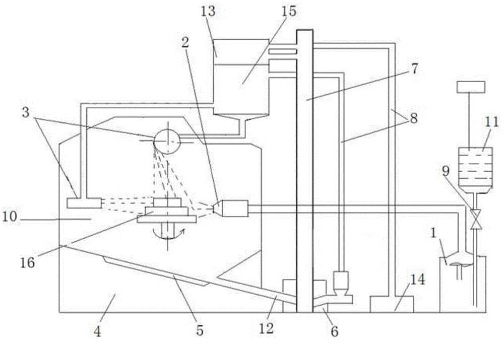
[0047] A method for hot air jet heating and shot peening to realize nitriding, comprising the following steps:

[0048] (1) Clean the dirt on the surface of the parts with gasoline, alcohol or acetone, install the cleaned parts into the chemical heat treatment furnace, leave a distance of 15mm between the surfaces of the parts that need to be nitrided, and the surface that does not need to be nitrided Close to each other to save space;

[0049] (2) Nitriding treatment: Spray nitriding atmosphere on the surface of the part to remove the air around the part; heat the ammonia gas to 300°C through the hot air flow generator, and spray it to the surface of the part through the hot air flow nozzle to heat the surface of the part at high speed. At the same time, Use the shot blasting machine to spray the round steel wire cut shot onto the surface of the part to create crystal defects on the metal surface; the diameter of the steel cut shot is 0.51mm, and at the same time, the hot air...

Embodiment 2

[0052] A method for hot air jet heating and shot peening to realize nitriding, comprising the following steps:

[0053] (1) Clean the dirt on the surface of the parts with gasoline, alcohol or acetone, install the cleaned parts in the chemical heat treatment furnace, leave a distance of 25mm between the surfaces of the parts that need to be nitrided, and the surface that does not need to be nitrided Close to each other to save space;

[0054] (2) Nitriding treatment: Nitriding atmosphere is sprayed on the surface of the parts in the furnace to remove the air around the parts; the ammonia gas is heated to 500°C through the hot air flow generator, and sprayed to the surface of the parts through the hot air flow nozzle to heat the surface of the parts at high speed. At the same time, use the shot blasting machine to spray the round steel wire cut shot onto the surface of the part to create crystal defects on the metal surface; the diameter of the steel cut shot is 2.0mm, and at t...

Embodiment 3

[0057] A method for hot air jet heating and shot peening to realize nitriding, comprising the following steps:

[0058] (1) Clean the dirt on the surface of the parts with gasoline, alcohol or acetone, install the cleaned parts in the chemical heat treatment furnace, leave a distance of 40mm between the surfaces of the parts that need to be nitrided, and the surface that does not need to be nitrided Close to each other to save space;

[0059] (2) Nitriding treatment: spray nitriding atmosphere to the parts in the furnace to remove the air around the parts; heat the ammonia gas to 400°C through the hot air flow generator, and spray it to the surface of the parts through the hot air flow nozzle to heat the surface of the parts at high speed, and at the same time , using a shot blasting machine to spray round steel wire cut shot onto the surface of the part to create crystal defects on the metal surface; the diameter of the steel cut shot is 1.0mm, and at the same time, the hot a...


PUM

PropertyMeasurementUnit
diameteraaaaaaaaaa
thicknessaaaaaaaaaa
depthaaaaaaaaaa

Abstract

The invention discloses a method for realizing nitriding or carburizing by thermal airflow jetting heating and shot blasting. Crystal defects on the surface of manufactured metal can be controlled, and surfaces of components are precisely heated at high speed. The method comprises the following steps of: (1) installing the cleaned components in a chemical thermal treatment furnace, keeping the spacing distance of 15-100mm between the surfaces of the components needing nitriding or carburizing, and abutting the surfaces not needing nitriding or carburizing so as to save the space; (2) nitriding or carburizing: heating a nitriding agent to 300-500 DEG C or a carburizing agent to 650-800 DEG C by using a thermal airflow generator, jetting to the surfaces of the components through a thermal airflow nozzle so as to heat surface layers of the components at high speed; at the same time, jetting balls to the surfaces of the components by using a shot blasting machine so as to manufacture the crystal defects on the surface layers of the manufactured metal simultaneously with increasing the surface temperature of the components, wherein the nitriding time is 0.5-6 hours, and the carburizing time is 0.5-4 hours; and (3) cooling after nitriding or carburizing.

Description

technical field [0001] The invention relates to a method for realizing nitriding or carburizing, in particular to a method for realizing nitriding or carburizing by hot air jet heating and shot peening. Background technique [0002] Nitriding and carburizing are two very common metal surface heat treatment methods. Although the medium and scope of application are different, the treatment process is quite similar. [0003] Nitriding is to place the steel piece in an active medium containing nitrogen, and at a certain temperature, the nitrogen atoms diffuse into the surface of the steel piece, thereby forming a layer of nitrided layer structure to improve the hardness of the layer. Chemical heat treatment process with various properties such as wear resistance, corrosion resistance and fatigue strength. [0004] During nitriding, we provide heat to the nitriding environment to obtain active nitrogen atoms in the infiltrating agent and increase the vibration amplitude of the m...

Claims


Application Information

Patent Timeline
Patent Type & Authority Patents(China)
IPC IPC(8): C23F17/00C23C8/20C23C8/24C21D7/06
Inventor 崔建军万桂怡崔潇
Owner SHANDONG UNIV
Learn More