
Microfuel cell having anodic and cathodic microfluidic channels and related methods

a microfluidic channel and microfuel cell technology, applied in the field of portable fuel cells, can solve the problems of overlief of anodic catalyst/electrode, anodic diffusion layer, etc., and achieve the effects of enhancing the power density of the microfuel cell, ensuring the structural integrity of the substrate, and avoiding overflowing of the anodic diffusion layer

Active Publication Date: 2006-04-18
STMICROELECTRONICS SRL
View PDF23 Cites 3 Cited by
  • Summary
  • Abstract
  • Description
  • Claims
  • Application Information

AI Technical Summary

Benefits of technology

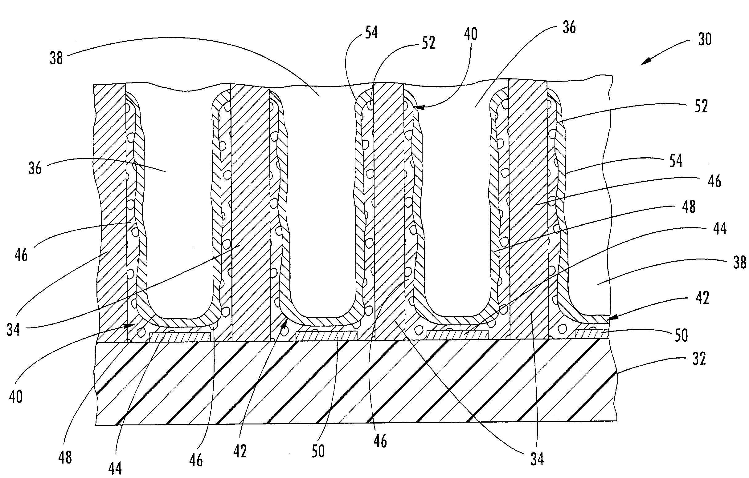
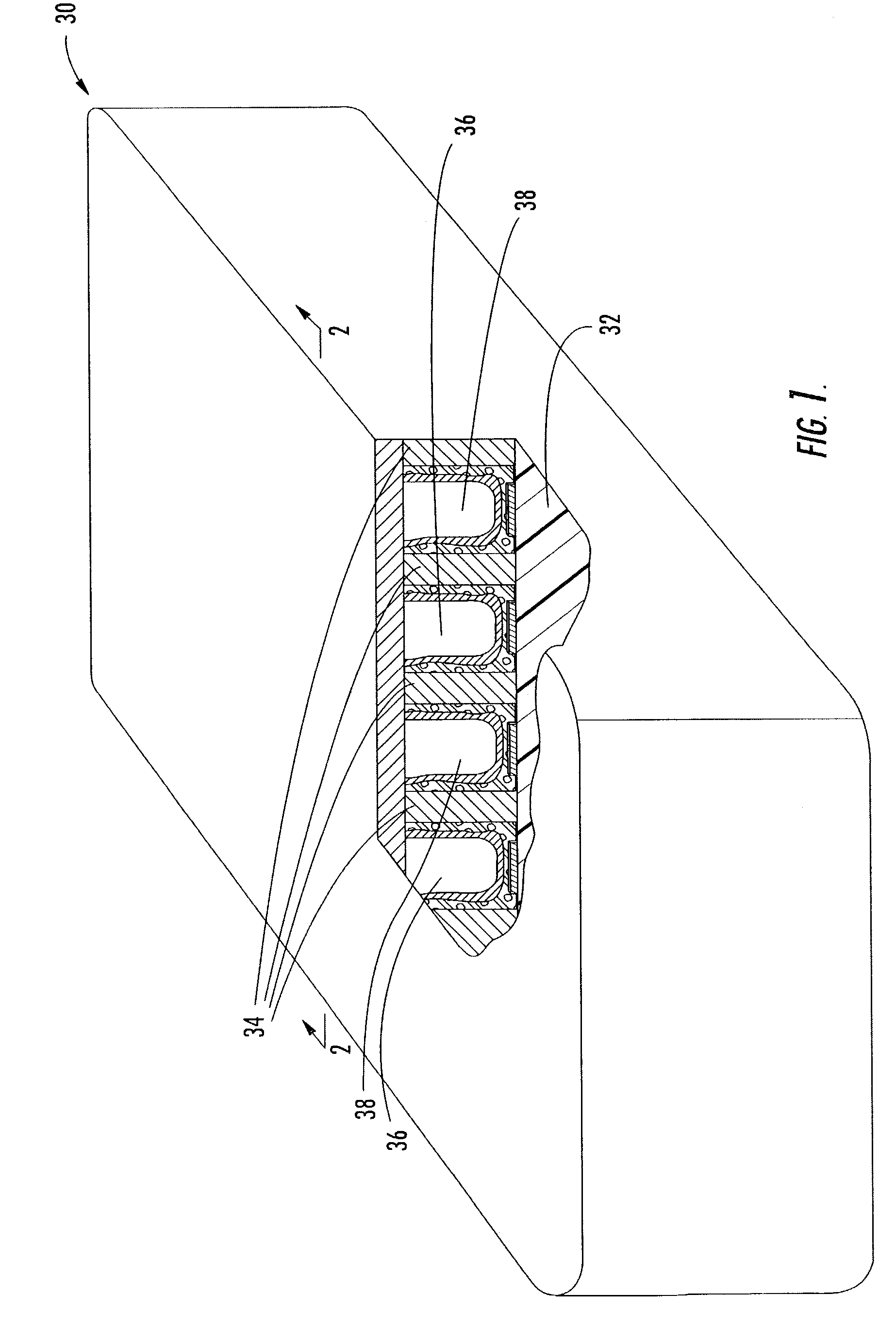
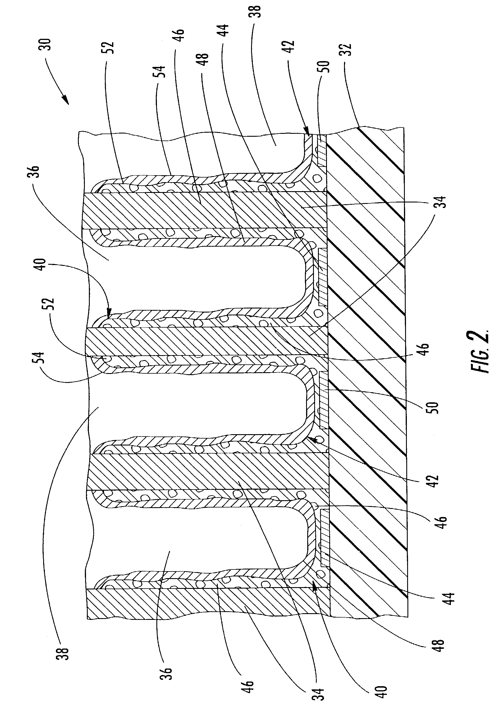
[0009]This and other objects, features, and advantages in accordance with the present invention are provided by a microfuel cell comprising in some embodiments a plurality of spaced-apart proton exchange media (PEM) dividers extending outwardly from a substrate to define a plurality of anodic and cathodic microfluidic channels that carry, respectively, anodic and cathodic reactants. The plurality of spaced-apart PEM dividers obviates the need to form channels in a substrate. One advantage is that the structural integrity of the substrate is not sacrificed for the sake of higher power density. Conversely, the catalyst surface-to-volume ratio of the microfuel cell may be increased to thereby further enhance the power density of the microfuel cell. The arrangement of the PEM dividers further permits the reactants to be carried in counterflow, which provides for better cooling of the microfuel cell.

Problems solved by technology

Additionally, an anodic diffusion layer may overlie the anodic catalyst / electrode.

Method used


Image

  • Microfuel cell having anodic and cathodic microfluidic channels and related methods
  • Microfuel cell having anodic and cathodic microfluidic channels and related methods
  • Microfuel cell having anodic and cathodic microfluidic channels and related methods

Examples


Embodiment Construction

[0027]The present invention will now be described more fully hereinafter with reference to the accompanying drawings, in which preferred embodiments of the invention are shown. This invention may, however, be embodied in many different forms and should not be construed as limited to the embodiments set forth herein. Rather, these embodiments are provided so that this disclosure will be thorough and complete, and will fully convey the scope of the invention to those skilled in the art. Like numbers refer to like elements throughout.

[0028]Referring to FIGS. 1–3, a microfuel cell 30 according to the present invention is now described. The microfuel cell 30 illustratively includes a substrate 32 and a plurality of spaced-apart PEM dividers 34 extending outwardly from the substrate. The PEM dividers 34 define a plurality of anodic and cathodic microfluidic channels 36, 38 for carrying, respectively, an anodic reactant and a cathodic reactant. The microfuel cell 30 further illustratively ...


PUM


Abstract

A microfuel cell includes a substrate and a plurality of spaced-apart PEM dividers extending outwardly to define anodic and cathodic microfluidic channels. An anodic catalyst / electrode lines at least a portion of the anodic microfluidic channels, and a cathodic catalyst / electrode lines at least a portion of the cathodic microfluidic channels. Each anodic and cathodic catalyst / electrode may extend beneath an adjacent portion of a PEM divider in some embodiments. Alternately, the microfuel cell may include a plurality of stacked substrates, in which a first substrate has first microfluidic fuel cell reactant channels. A PEM layer may be adjacent the first surface of the first substrate, an anodic catalyst / electrode layer may be adjacent one side of the PEM layer, and a cathodic catalyst / electrode layer may be adjacent an opposite side of the PEM layer. An adhesive layer may secure the first substrate to an adjacent substrate defining at least a second microfluidic fuel cell reactant channel.

Description

FIELD OF THE INVENTION[0001]The present invention relates to the field of portable power sources, and, more particularly, to portable fuel cells.BACKGROUND OF THE INVENTION[0002]A fuel cell typically comprises a pair of catalyst / electrodes and an ion-transporting electrolyte sandwiched between the catalyst / electrodes. Each catalyst / electrode, for example, may be a catalyst layer over which an electrode layer extends. Alternately, each may comprise an electrode layer impregnated with a catalyst.[0003]One catalyst / electrode may serve as a reactive or catalytic site for oxidizing a fuel such as hydrogen (H2), methanol (CH3OH), or other hydrocarbon, while the other serves as a catalytic site for reducing a reactant, typically, air or pure oxygen (O2). The electrolyte is typically a proton exchange media (PEM) that blocks the flow of electrons while conducting positively charged ions such as hydrogen ions.[0004]The oxidation-reduction reactions at the respective catalytic sites thus resu...

Claims


Application Information

Patent Timeline
IPC IPC(8): H01M8/10H01M8/04H01M8/24H01M4/86H01M4/88H01M4/94H01M8/00H01M8/02H01M8/14
CPCH01M4/8626H01M8/0247H01M8/241H01M8/1002Y02E60/521H01M8/1007Y02P70/50Y02E60/50H01M8/2404
Inventor LO PRIORE, STEFANOPALMIERI, MICHELEMASTROMATTEO, UBALDO
Owner STMICROELECTRONICS SRL
Learn More