
Electrophotographic image forming apparatus

Active Publication Date: 2006-04-18
RICOH KK
View PDF41 Cites 9 Cited by
  • Summary
  • Abstract
  • Description
  • Claims
  • Application Information

AI Technical Summary

Benefits of technology

[0013]Accordingly, an object of the present invention is to provide an electrophotographic image forming apparatus which stably producing high-resolution images without produces abnormal images when repeatedly used at a high speed, specifically by eradicating the electrical deterioration of the photoreceptor due to a reverse charge in a transferer.
[0014]Another object of the present invention is to provide an electrophotographic image forming apparatus which maintains the specific high sensitivity of the titanylphthalocyanine even when a non-halide solvent is used for the charge transport layer coating liquid.
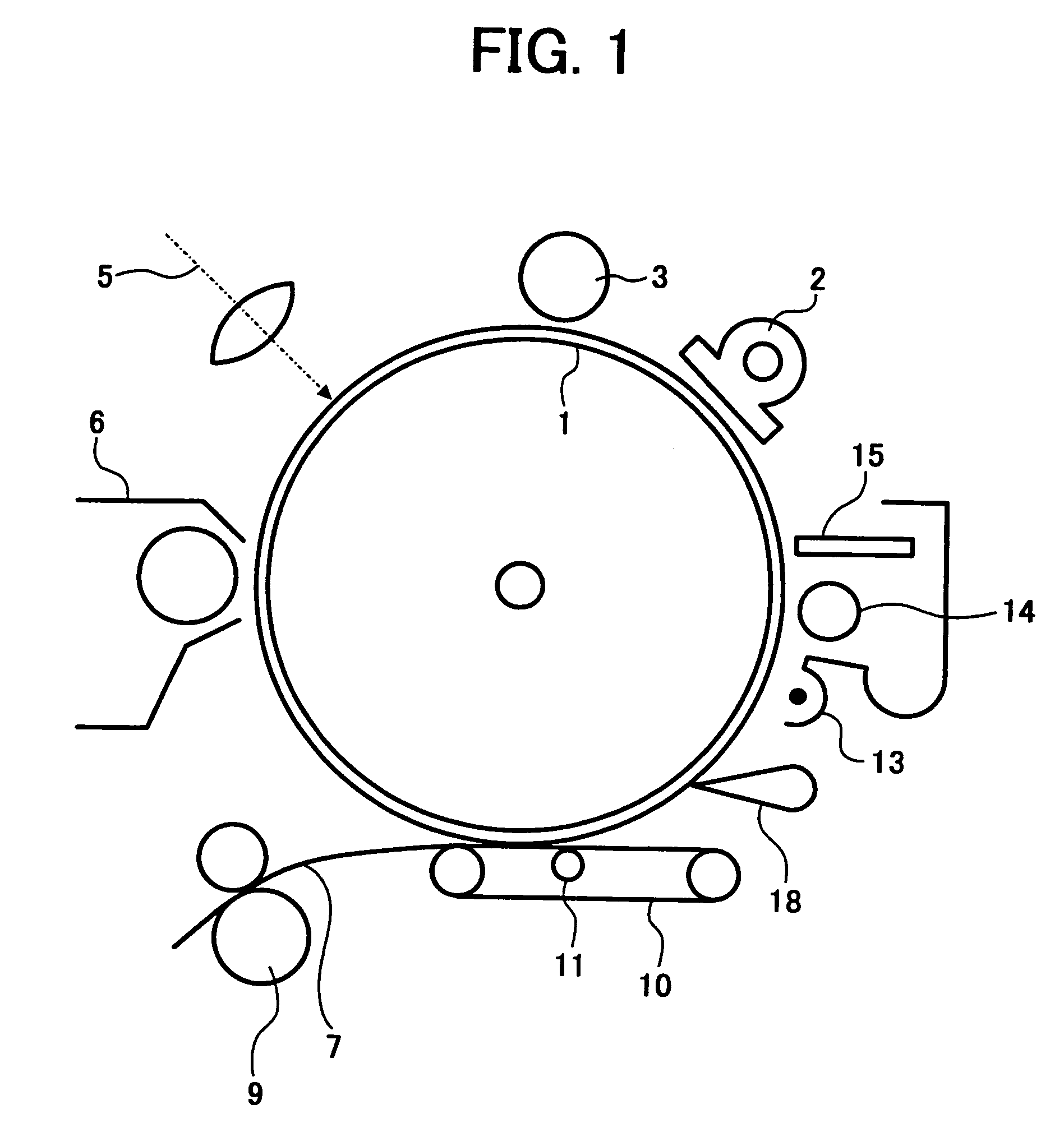
[0015]Briefly these objects and other objects of the present invention as hereinafter will become more readily apparent, can be attained by an electrophotographic image forming apparatus including at least an electrophotographic photoreceptor which includes at least an electroconductive substrate; a charge generation layer overlying the substrate; a charge transport layer overlying the charge generation layer, a charger charging the electrophotographic photoreceptor; an irradiator irradiating the electrophotographic photoreceptor to form an electrostatic latent image thereon; an image developer developing the electrostatic latent image with a developer including at least a toner to form a toner image on the electrophotographic photoreceptor; and a transferer transferring the toner image onto a transfer sheet, wherein the transferer applies an electrical current of not less than 65 μA to the electrophotographic photoreceptor, and wherein the charge generation layer includes a titanylphthalocyanine crystal having a CuKα 1.542 Å X-ray diffraction spectrum including plural diffraction peaks, wherein a maximum diffraction peak is observed at a Bragg (2θ) angle of 27.2°; main peaks are observed at 9.4°, 9.6° and 24.0°; and a minimum diffraction peak is observed at 7.3°; and no diffraction peak is observed at an angle greater than 7.3° and less than 9.4°, wherein said angles may vary by ±0.2° and the minimum interval where no peak is observed between required peaks at 7.3 and 9.4 is 2.0 degrees absolute or more. The transfer current of 65 μA is larger than a typical transfer current, and is more effectively used in a high-speed digital electrophotographic image forming apparatus, preferably a high-speed digital electrophotographic image forming apparatus having a linear speed not less than 200 mm / sec. A detailed reason for the effect of the present invention has not been clarified, but is believed to come from the high chemical stability of the titanylphthalocyanine crystal of the present invention.

Problems solved by technology

However, objects of the publications are decreasing the problems caused by a large current applied to a photoreceptor and the upper limits thereof are at most 50 μA.
This is because a reverse bias for the transfer causes electrostatic deterioration of the photoreceptor as mentioned above.
Although effective means for controlling the process are available, effective photoreceptors taking advantage of the means are not available.
Therefore, the toner still remains on the photoreceptor after being transferred, and a toner image faithful to an electrostatic latent image thereon cannot be transferred.

Method used


Image

  • Electrophotographic image forming apparatus
  • Electrophotographic image forming apparatus
  • Electrophotographic image forming apparatus

Examples


synthesis example 1

[0174]29.2 g of 1,3-diiminoisoindoline and 200 ml of sulfolane were mixed, and 20.4 g of titaniumtetrabutoxide were dropped into the mixture under a nitrogen gas stream. The mixture was gradually heated until the mixture had a temperature of 180° C. and was stirred for 5 hrs while the reaction temperature was maintained from 170 to 180° C. After the mixture was cooled, a precipitated material (powder) was filtered and washed with chloroform until the powder became blue. Next, the powder was washed with methanol several times, and further washed with hot water having a temperature of 80° C. several times to provide a crude titanylphthalocyanine pigment. The crude titanylphthalocyanine pigment was mixed in concentrated sulfonic acid which was present in an amount of 20 times as much as the amount of crude titanylphthalocyanine pigment and stirred to dissolve the pigment therein. The mixture was then dropped in ice water, which was present in an amount of 100 times as much as the mixtu...

synthesis example 2

[0184]A pigment was prepared in accordance with the method disclosed in Example 1 in Japanese Laid-Open Patent Publication No. 1-299874 (Japanese patent No. 2512081). Namely, the wet cake prepared in Synthesis Example 1 was dried and 1 g of the dried material was included in 50 g of polyethylene glycol. The mixture was dispersed by a sand mill for 1 hr with 100 g of glass beads. After the crystal conversion, the dispersed material was washed with a diluted sulfuric acid and an aqueous solution of ammonium hydroxide in this order, and dried to provide a pigment. This is Pigment 7.

synthesis example 3

[0185]A pigment was prepared in accordance with the method disclosed in Production Example 1 in Japanese Laid-Open Patent Publication No. 3-269064 (Japanese Patent No. 258468). Namely, the wet cake prepared in Synthesis Example 1 was dried, and after 1 g of the dried material was stirred in a mixed solvent of 10 g of ion exchange water and 1 g of monochlorobenzene for 1 hr at 50° C., the mixture was washed with methanol and ion exchange water and dried to provide a pigment.


PUM


Abstract

An electrophotographic image forming apparatus comprising:an electrophotographic photoreceptor comprising:an electroconductive substrate;a charge generation layer; anda charge transport layer in this order,a charger;an irradiator;an image developer; anda transferer applying an electric current not less than 65 μA to the electrophotographic photoreceptor,wherein the charge generation layer comprises titanylphthalocyanine crystals having a CuKα 1.542 Å X-ray diffraction spectrum having plural diffraction peaks, wherein a maximum diffraction peak is observed at a Bragg (2 θ) angle of 27.2°; main peaks are observed at 9.4°, 9.6° and 24.0°; and a minimum diffraction peak is observed at 7.3°; and no diffraction peak is observed at an angle greater than 7.3° and less than 9.4°, wherein said angles may vary by ±0.2° and the minimum interval where no peak is observed between required peaks at 7.3 and 9.4 is 2.0 degrees absolute or more.

Description

BACKGROUND OF THE INVENTION[0001]1. Field of the Invention[0002]The present invention relates to an electrophotographic image forming apparatus, and more particularly to an electrophotographic image forming apparatus using an electrophotographic photoreceptor formed of a charge transport layer overlying a charge generation layer and including at least a specific titanylphthalocyanine crystal, wherein a toner image is transferred with the application of not less than a specific current.[0003]2. Discussion of the Background[0004]Recently, information processing system apparatuses using an electrophotographic image forming method have been significantly progressed. Particularly, impressive improvements in print quality and reliability have been made in optical printers which optically record information by converting the information into a digital signal. This digital recording technology is applied not only to printers but also to conventional copiers, and so-called digital copiers ha...

Claims


Application Information

Patent Timeline
IPC IPC(8): G03G5/00G03G15/02G03G15/047G03G5/06
CPCG03G5/0696G03G2215/00957
Inventor TODA, NAOHIRONIIMI, TATSUYA
Owner RICOH KK
Learn More