Immersion lithography methods using carbon dioxide

a technology of carbon dioxide and lithography, applied in the field of immersion lithography methods using carbon dioxide, can solve the problems of reducing the size of microelectronic devices, the cost of continuing to reduce the wavelength of radiation sources, and the difficulty in designing an all-reflective camera that achieves lithographic-quality imaging, etc., and achieve the effect of improving conta

Inactive Publication Date: 2006-04-18
THE UNIV OF NORTH CAROLINA AT CHAPEL HILL
View PDF10 Cites 74 Cited by
  • Summary
  • Abstract
  • Description
  • Claims
  • Application Information

AI Technical Summary

Benefits of technology

[0015]In still other embodiments, a solid immersion film is placed on (contacted to) the photoresist layer and the photoresist layer is imaged through the solid immersion film. In some embodiments, the solid immersion film includes carbon dioxide and at least one solid immersion film compound. However, in other embodiments, the solid immersion film need not comprise carbon dioxide. Moreover, in still other embodiments, an immersion fluid layer is first formed on the photoresist layer and the solid immersion film is then placed on the immersion fluid la

Problems solved by technology

One of the primary hurdles in achieving the much sought after size reduction of microelectronic devices is in the area of photolithography.
The cost of continuing to reduce the wavelength of the radiation source may be enormous.
Designing an all-reflective camera that achieves lithographic-quality imaging may be more diff

Method used


Image

  • Immersion lithography methods using carbon dioxide
  • Immersion lithography methods using carbon dioxide
  • Immersion lithography methods using carbon dioxide

Examples


Embodiment Construction

[0021]The present invention now will be described more fully hereinafter with reference to the accompanying drawings, in which embodiments of the invention are shown. However, this invention should not be construed as limited to the embodiments set forth herein. Rather, these embodiments are provided so that this disclosure will be thorough and complete, and will fully convey the scope of the invention to those skilled in the art. In the drawings, the thickness of layers and regions are exaggerated for clarity. Like numbers refer to like elements throughout. It will be understood that when an element such as a layer, region or substrate is referred to as being “on” or extending “onto” another element, it can be directly on or extend directly onto the other element or intervening elements may also be present. In contrast, when an element is referred to as being “directly on” or extending “directly onto” another element, there are no intervening elements present.

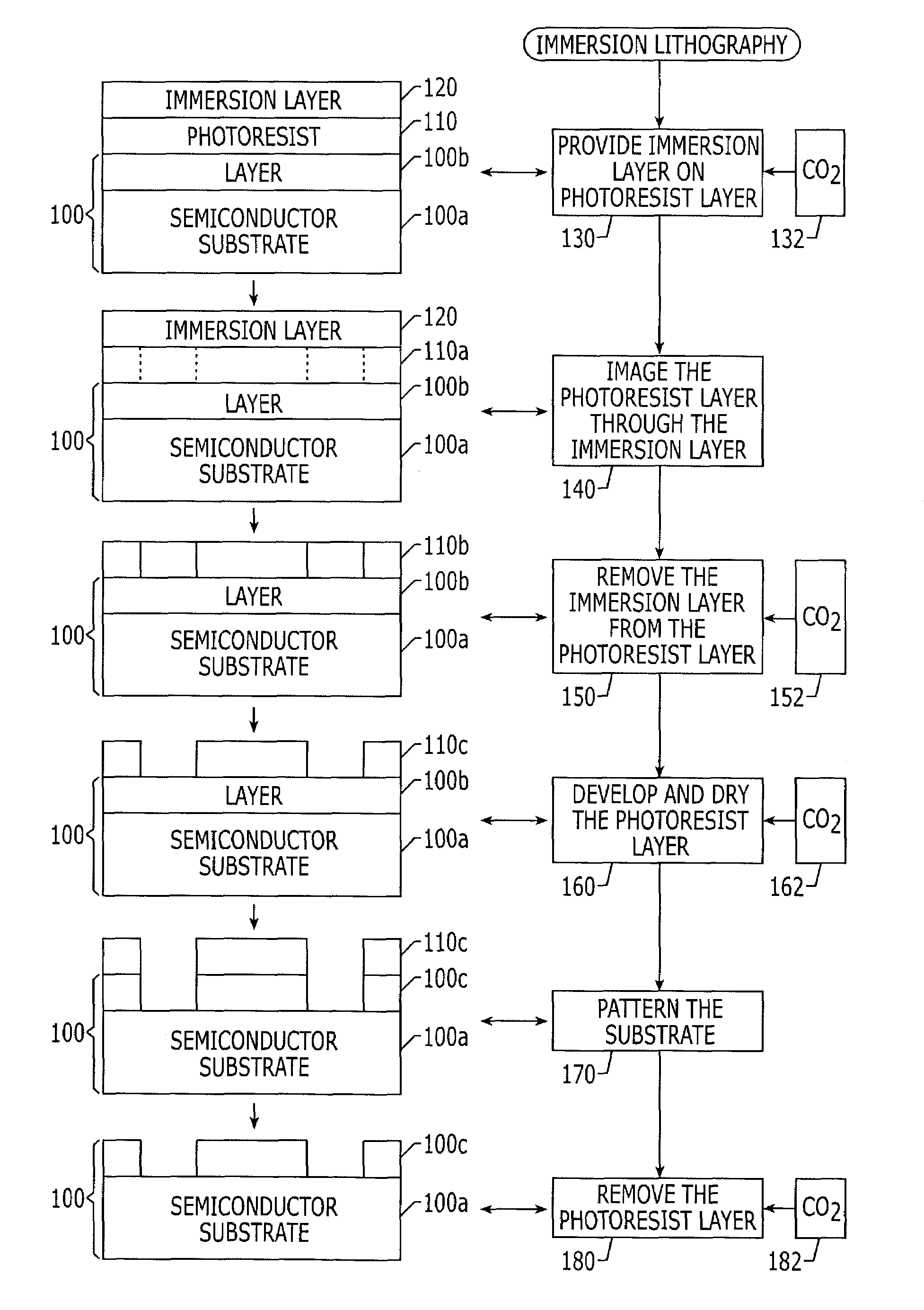
[0022]FIG. 1 is a flow...


PUM


Abstract

A substrate is patterned by performing immersion lithography on a photoresist layer on the substrate using carbon dioxide. The immersion layer may be provided and/or removed and/or the photoresist layer may be developed, dried and/or removed using carbon dioxide. The immersion layer can include liquid and/or solid immersion layers. The need for organic solvents in immersion lithography can thereby be reduced or eliminated.

Description

FIELD OF THE INVENTION[0001]The present invention relates to methods of patterning a photoresist layer on a substrate as well as methods of removing an immersion layer from a photoresist layer.BACKGROUND OF THE INVENTION[0002]To satisfy the ever-increasing desire for faster and smaller electronic devices such as personal computers, it has become desirable to increase the number of microelectronic devices such transistors on a chip without increasing the size of the chip. Accordingly, it is desirable to continually strive to reduce the size of the microelectronic devices.[0003]One of the primary hurdles in achieving the much sought after size reduction of microelectronic devices is in the area of photolithography. For decades, photolithography has been utilized to pattern photoresists in the manufacture of microelectronic devices. The resolution of the image formed on a photoresist layer using photolithography generally is directly proportional to the wavelength of the radiation sour...

Claims


Application Information

Patent Timeline
IPC IPC(8): G03F7/00G03F7/20G03F7/32
CPCG03F7/2041G03F7/70341G03F7/32
Inventor ROLLAND, JASON P.DESIMONE, JOSEPH P.
Owner THE UNIV OF NORTH CAROLINA AT CHAPEL HILL
Why Eureka
Try Eureka