Low voltage differential signaling device with feedback compensation

Active Publication Date: 2006-04-18
VIA TECH INC
View PDF4 Cites 59 Cited by
  • Summary
  • Abstract
  • Description
  • Claims
  • Application Information

AI Technical Summary

Benefits of technology

[0008]Therefore, it is an object of the present invention to provide a low voltage differential signali

Problems solved by technology

Unfortunately, the signal drift problem resulting from the manufacturing factors of the above-

Method used


Image

  • Low voltage differential signaling device with feedback compensation
  • Low voltage differential signaling device with feedback compensation
  • Low voltage differential signaling device with feedback compensation

Examples


Embodiment Construction

[0026]The present invention will now be described more specifically with reference to the following embodiments. It is to be noted that the following descriptions of preferred embodiments of this invention are presented herein for purpose of illustration and description only; it is not intended to be exhaustive or to be limited to the precise form disclosed.

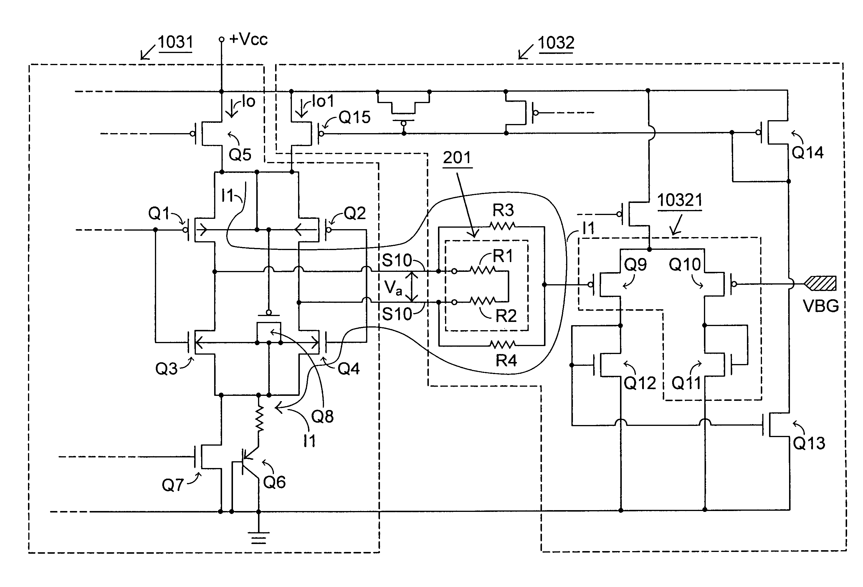
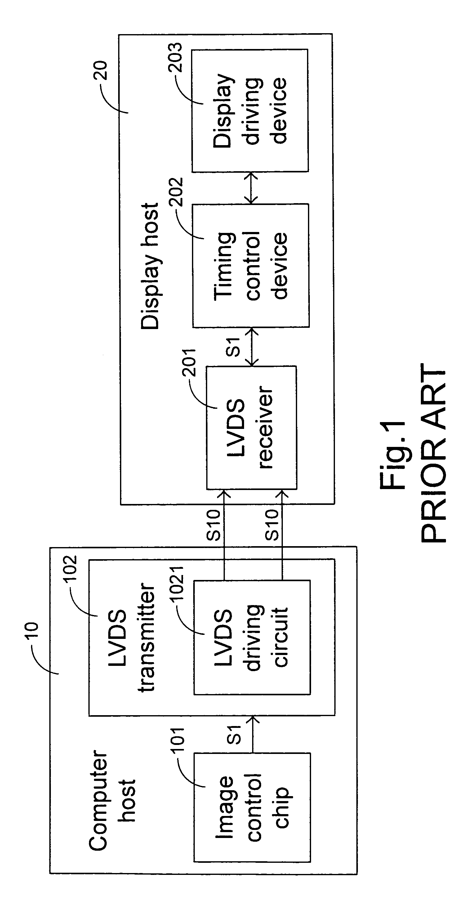
[0027]Please refer to FIG. 3, an embodiment of the LVDS transmitting device according to the present invention is shown. The LVDS transmitting device 103 is applied to a system comprising a computer host 10 and a display host 20 such as a liquid crystal display (LCD). An image control chip 101 inside the computer host 10 outputs a digital image signal S1 to the LVDS transmitting device 103 to be modulated into an analog image signal S10 having a swing as low as 300 mV˜350 mV. Then, via an LVDS driving circuit 1031, the analog image signal S10 is outputted to an LVDS receiver 201.

[0028]The LVDS transmitting device 103 according to...


PUM


Abstract

A low voltage different signaling (LVDS) includes an LVDS transmitter and an LVDS receiver. The LVDS transmitter includes a feedback compensation circuit, which adjusts and stabilizes the analog image signal to be transmitted to the LVDS receiver according to the voltage difference of the analog image signal and a base signal. The feedback compensation circuit includes a voltage-to-current converting circuit and a pair of current mirror circuits.

Description

FIELD OF THE INVENTION[0001]The present invention relates to a low voltage differential signaling device, and more particularly to a low voltage differential signaling device with feedback compensation.BACKGROUND OF THE INVENTION[0002]With the highly development of the internet, various kinds of data transmission on the internet are required. Therefore, a diversity of communication and transmission means are developed and used to facilitate the work on the internet. Particularly for the means requiring large bandwidth for supporting serial data flow, e.g. digital display, high resolution frame or color graphics, the transmission of the large amount of data relies much on the analog technique to design circuit system and support data transmission. Low voltage differential signaling (LVDS) is one of the analog techniques for transmission. This technique can be utilized to design hybrid signaling systems. The LVDS technique is a high-speed analog circuiting technique, which supports da...

Claims


Application Information

Patent Timeline
IPC IPC(8): H03K19/094G09G5/00H03K5/24H04N7/015
CPCH04L25/0272H03K19/018528G09G5/006
Inventor LO, HUA-JANLIN, SIMONCHEN, JUNECHU, WEI-SHANG
Owner VIA TECH INC
Why Eureka
Try Eureka