System and method for programming a memory cell

a memory cell and programming system technology, applied in the field of semiconductor fuses and systems and methods for programming semiconductor fuses, can solve the problems of programmed fuse contamination, increased complexity and chip size of non-volatile memory manufacturing techniques, etc., and achieves high repeatability and reliability.

Inactive Publication Date: 2007-05-01
AVAGO TECH INT SALES PTE LTD
View PDF5 Cites 72 Cited by
  • Summary
  • Abstract
  • Description
  • Claims
  • Application Information

AI Technical Summary

Benefits of technology

[0013]Such application of current provides high repeatability and reliability as compared to conventional voltage based programming. The conventional voltage based programming requires relatively high voltages (>2.5V), which are incompatible with sub-micron CMOS technology. The present invention's systems and methods are less susceptible to electrostatic discharge damage of the fuse via input current source.

Problems solved by technology

The non-volatile memory manufacturing techniques increase the complexity and chip size.
One of the disadvantages of this method is that the programmed fuse is prone to contamination.

Method used


Image

  • System and method for programming a memory cell
  • System and method for programming a memory cell
  • System and method for programming a memory cell

Examples


Embodiment Construction

Table of Contents

1. Introduction.

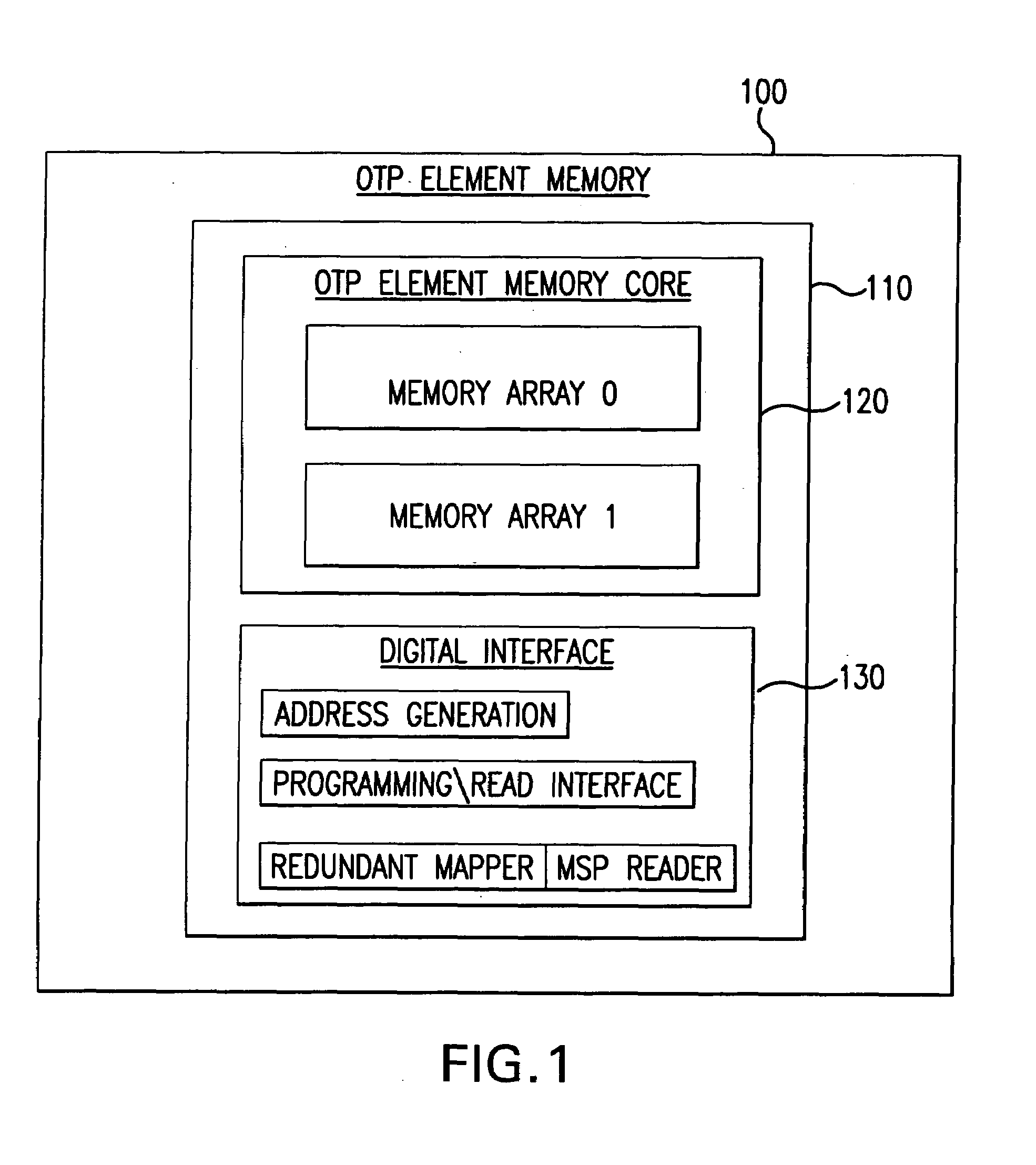
2. One-Time Programmable (OTP) Memory Element—System Structure.

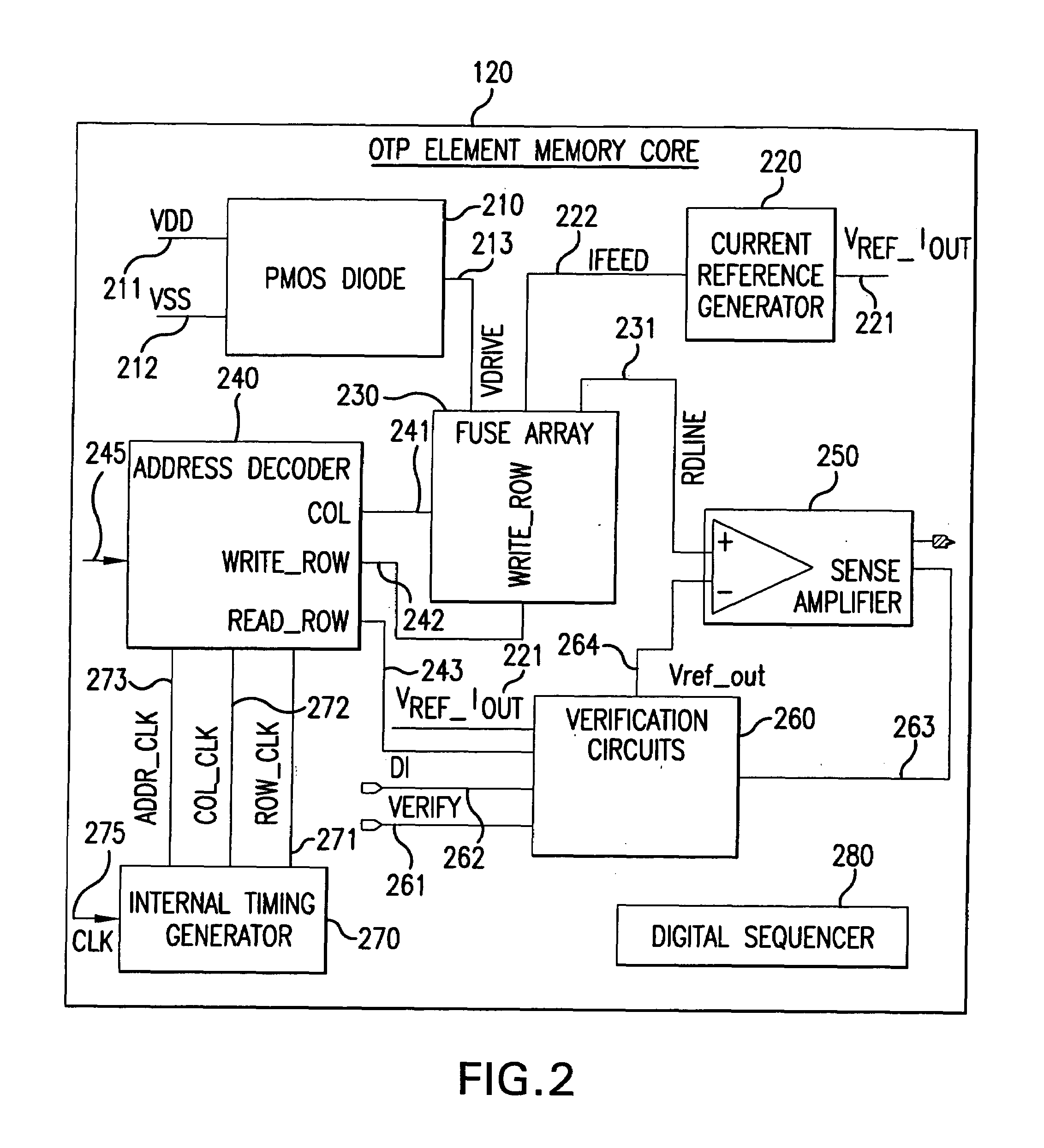
[0046]a. OTP Memory Core.

[0047]b. Row-column Matrix Memory Array Scheme.

[0048]c. Address Decoder.

[0049]d. Internal Timing Generator.

[0050]e. Verification Circuit.

[0051]f. PMOS Diode.

3. OTP Memory Element in-System Operation.

[0052]a. Programming Mode.

[0053]b. Reading Mode.

[0054]c. Verification mode.

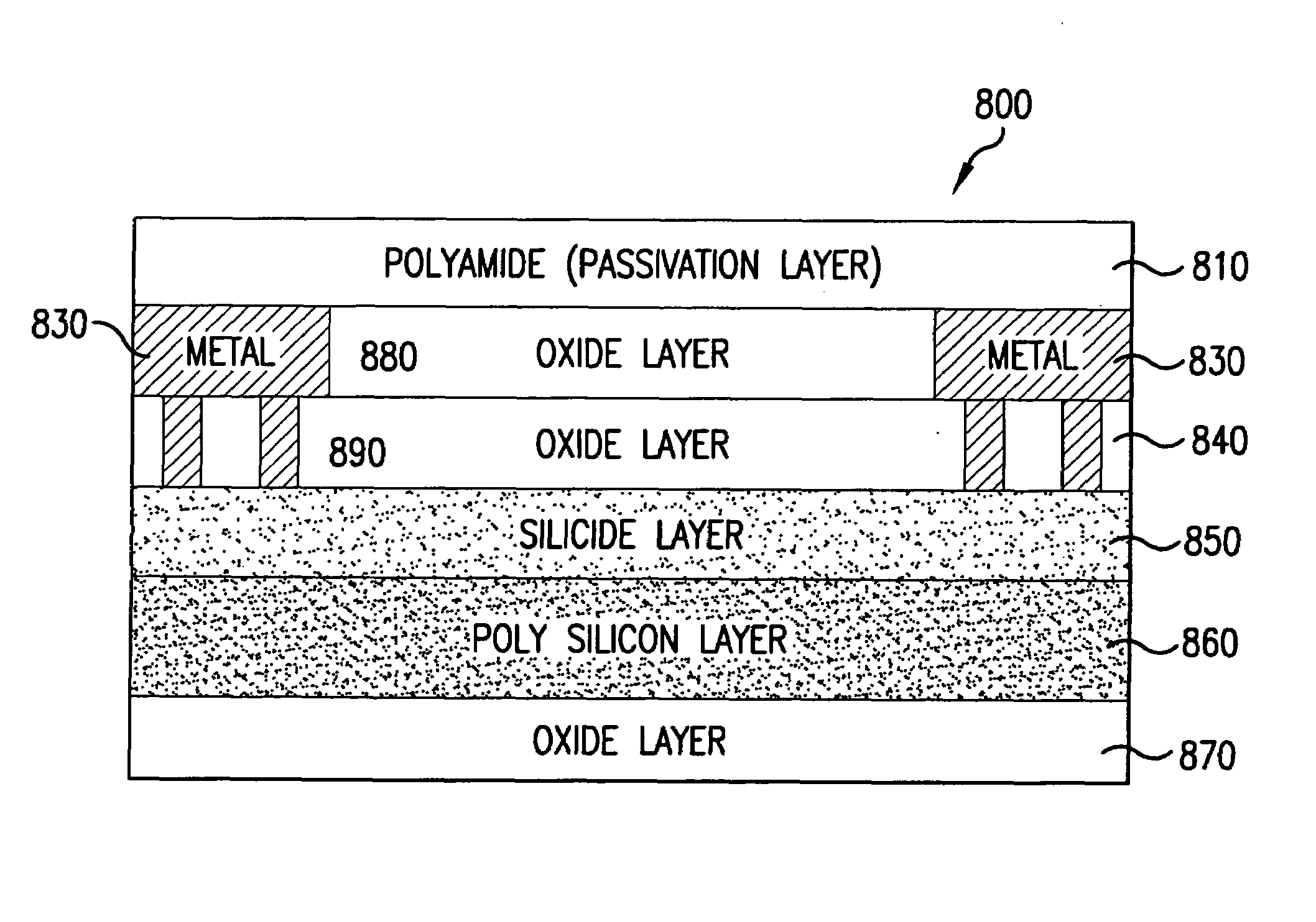
4. Poly-Si Fuse Design.

5. Conclusion.

[0055]While the present invention is described herein with reference to illustrative embodiments for particular applications, it should be understood that the invention is not limited thereto. Those skilled in the art with access to the teachings provided herein will recognize additional modifications, applications, and embodiments within the scope thereof and additional fields in which the present invention would be of utility.

1. Introduction.

[0056]The present invention relates to semiconductor programmable elements. In particular, the present invention is d...


PUM


Abstract

The present invention relates to systems and methods for programming a memory cell. More specifically, the present invention relates to a controlled application of current to a memory cell over a controlled time period. The invention utilizes a current mirror configuration having a first transistor and a second transistor, wherein the second transistor is coupled to the memory cell. Programming of the memory cell includes applying a voltage to the first transistor, whereby a first current is generated in the first transistor. A gate of the second transistor is coupled to the first transistor, whereby a second current is generated in the second transistor. The second current is proportional to the first current. The second current is provided to the memory cell, whereby the second current programs the memory cell.

Description

CROSS-REFERENCE TO RELATED APPLICATIONS[0001]This application claims priority to U.S. Provisional Patent Application No. 60 / 377,238, filed May 3, 2002, which is incorporated by reference herein in its entirety.[0002]This application is a continuation-in-part of a U.S. patent application Ser. No. 10 / 115,013, filed Apr. 4, 2002, now U.S. Pat. No. 6,580,156 to Akira et al. which is incorporated by reference herein in its entirety.BACKGROUND OF THE INVENTION[0003]1. Field of the Invention[0004]The present invention is directed to semiconductor fuses and systems and methods for programming semiconductor fuses.[0005]2. Background Art[0006]In the field of data storage, there are two main types of storage elements. The first type is volatile memory that has the information stored in a particular storage element, and the information is lost the instant the power is removed from a circuit. The second type is a nonvolatile storage element, in which the information is preserved even with the po...

Claims


Application Information

Patent Timeline
Patent Type & Authority Patents(United States)
IPC IPC(8): H01L27/10G11C5/00G11C17/00
CPCH01L23/5256H01L2924/0002H01L2924/00
Inventor LOW, KHIM L.BROOKS, TODD L.WOO, AGNESITO, AKIRA
Owner AVAGO TECH INT SALES PTE LTD
Why Eureka
Try Eureka