Three axes line-of-sight transducer

a transducer and three axes technology, applied in the field of sensors, can solve the problems of impede the development of small quick munitions, complicated processing, and ball actuation

Inactive Publication Date: 2006-04-25
RAYTHEON CO
View PDF6 Cites 103 Cited by
  • Summary
  • Abstract
  • Description
  • Claims
  • Application Information

AI Technical Summary

Problems solved by technology

The issue with this approach has been precise control of ball orientation.
The BJG, however, also has disadvantages that impede its development for small quick munitions.
These issues include very complicated processing, ball actuation cable reliability, stabilization for higher frequency excitation, source of small motor / encoders of sufficient accuracy and an excessive time period after power-up for gimbal initialization before use.
Small movement of the ball results in large movement of the rotor.
If the orientation calculation is in error, due to cable stretching, untimely data or other inequities, the ball will be driven to an erroneous orientation causing LOS errors and jitter.
Of course this is the case with any gimbal, but the ridged coupling between the ball and the motors prevents the integration or smoothing of high frequency errors by the gimbal's inertia.
One result of this iniquity is that as the gimbal excitation increases in frequency, where changes in body rate are not over-sampled by the rate sensor, the error in the orientation calculation increases.
The measurement of the ball position remotely, i.e. by measuring the actuation cable position, is a natural source for error and requires preflight initialization such that the system knows zero position of the encoders before operation.

Method used


Image

  • Three axes line-of-sight transducer
  • Three axes line-of-sight transducer
  • Three axes line-of-sight transducer

Examples


Embodiment Construction

[0027]Illustrative embodiments and exemplary applications will now be described with reference to the accompanying drawings to disclose the advantageous teachings of the present invention.

[0028]While the present invention is described herein with reference to illustrative embodiments for particular applications, it should be understood that the invention is not limited thereto. Those having ordinary skill in the art and access to the teachings provided herein will recognize additional modifications, applications and embodiments within the scope thereof and additional fields in which, the present invention would be of significant utility.

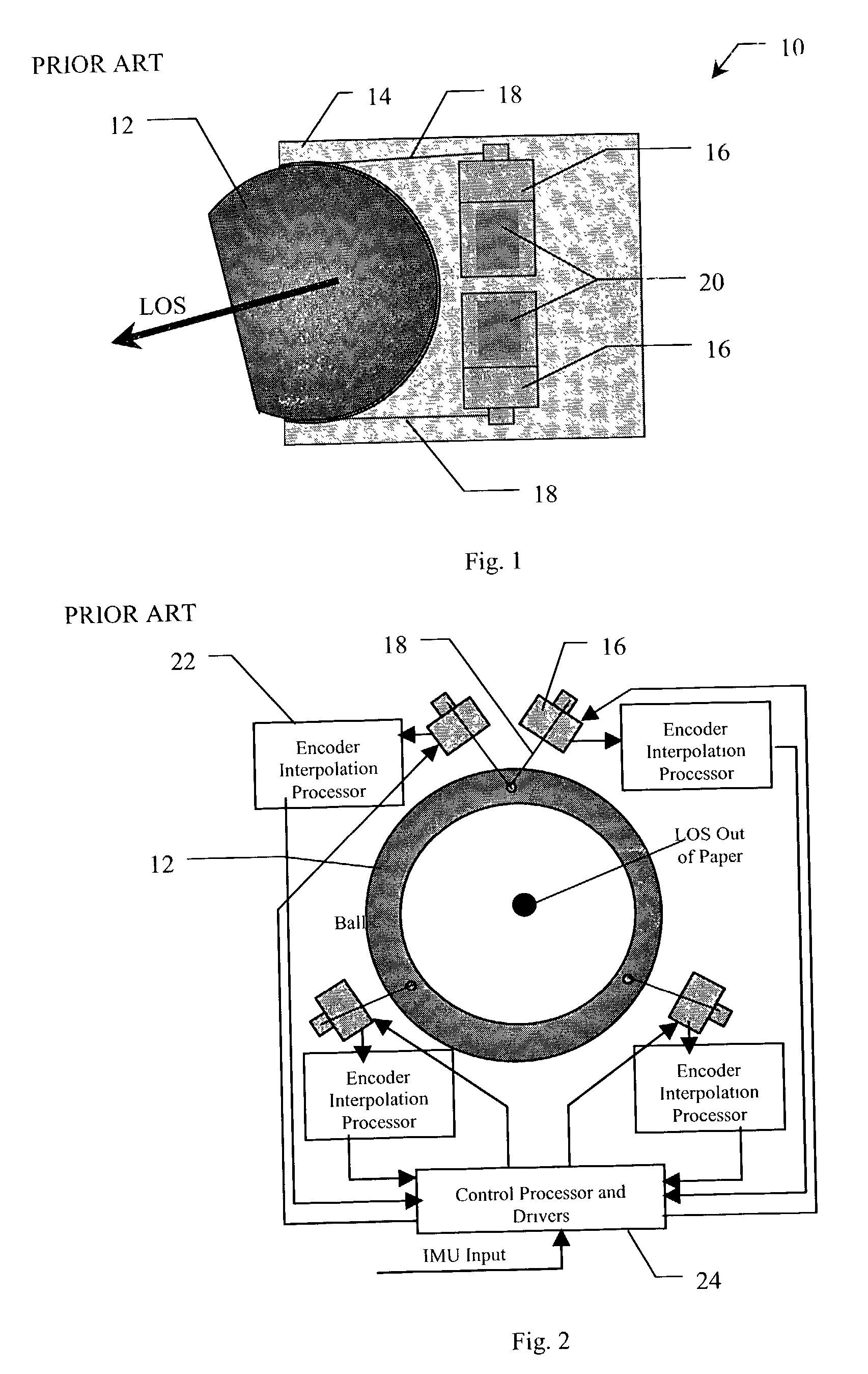
[0029]FIG. 1 is an illustration showing a basic BJG configuration 10 in accordance with conventional teachings. A ball 12 in a socket 14 has a ball orientation controlled by four motors 16 that pull on tendon cables 18 attached to the ball 12. Optical encoders 20 on the motors 16 sense ball orientation by measuring tendon length. To achieve the requi...


PUM


Abstract

A system and method for measuring orientation of an object. In the illustrative embodiment, the object is a ball (42) in a ball and socket type pointing and stabilization system. The novel system (40) includes an encoded pattern (46) applied to a portion of the surface of the ball (42), a pattern reader (44) which reads the pattern (46) off the ball (42) and outputs data representative of the pattern (46), and a processor (48) which decodes the data into orientation information. In the preferred embodiment, the pattern reader (44) is an electro-optical sensor, and the encoded pattern (46) includes a grid of dots (52) arranged in a first predetermined number of dot code cycles (58) wherein each dot code cycle (58) includes a second predetermined number of dots. The processor (48) includes an algorithm (100) which computes pitch, yaw, and roll angles from the pattern reader data.

Description

BACKGROUND OF THE INVENTION[0001]1. Field of the Invention[0002]The present invention relates to sensors. More specifically, the present invention relates to systems for measuring the relative position of a ball to a socket for any device using a ball and socket.[0003]2. Description of the Related Art[0004]The ball and socket type gimbal approach has been attractive for many years for pointing and stabilization systems (PSS) for seeker applications. The issue with this approach has been precise control of ball orientation. One of the three primary components in controlling the ball is accurate measurement of ball orientation.[0005]The ball joint gimbal (BJG) employs current art for ball and socket PSS. The basic BJG configuration has a ball in a socket with the ball orientation controlled by four motors that pull on tendon cables attached to the ball. Optical encoders on the motors sense ball orientation by measuring tendon length in an indirect line-of-sight (LOS) measurement appro...

Claims


Application Information

Patent Timeline
Patent Type & Authority Patents(United States)
IPC IPC(8): G01C19/54G01B11/26G01D5/34
CPCG01D5/34Y10T74/1264Y10T74/1229G01D2205/95
Inventor BAILEY, THEODORE B.
Owner RAYTHEON CO
Why Eureka
Try Eureka