
Energy transfer system for cold storage facilities

a technology of energy transfer system and cold storage facility, which is applied in the direction of defrosting, heating type, domestic cooling apparatus, etc., can solve the problems of heaving of the floor, freezing of the floor, and so as to prevent icing of the floor, reduce the energy required, and prevent the effect of icing

Inactive Publication Date: 2006-04-25
SCHULAK EDWARD R
View PDF10 Cites 14 Cited by
  • Summary
  • Abstract
  • Description
  • Claims
  • Application Information

AI Technical Summary

Benefits of technology

[0002]The present invention relates to cold storage facilities and, more particularly, to energy transfer systems for maintaining the floor of a cold storage facility at a desired temperature to eliminate underfloor icing and for reducing the operating temperature of the condenser and / or compressor in the cooling system and for cooling the exterior of the building.
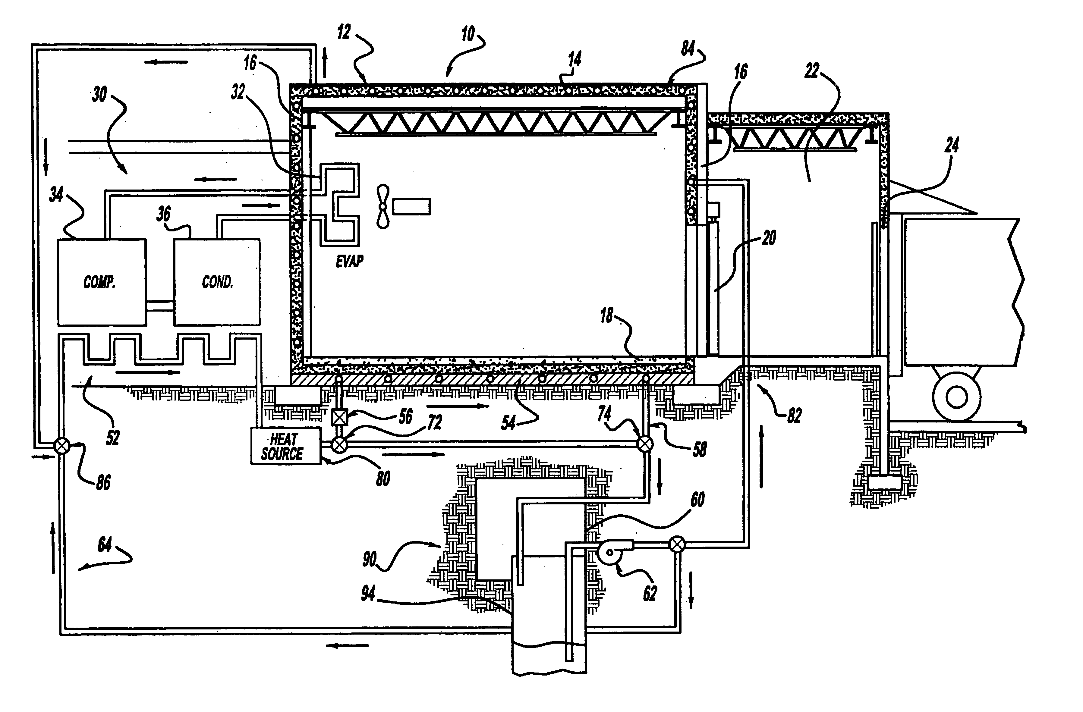
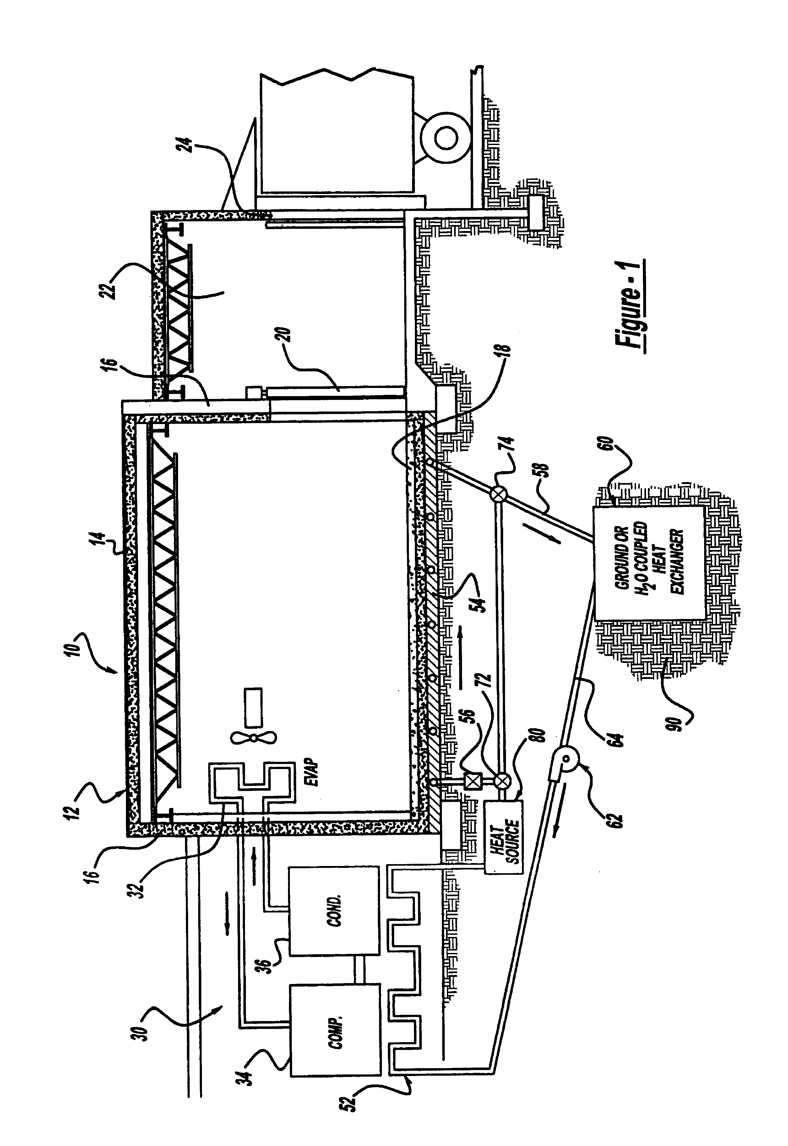
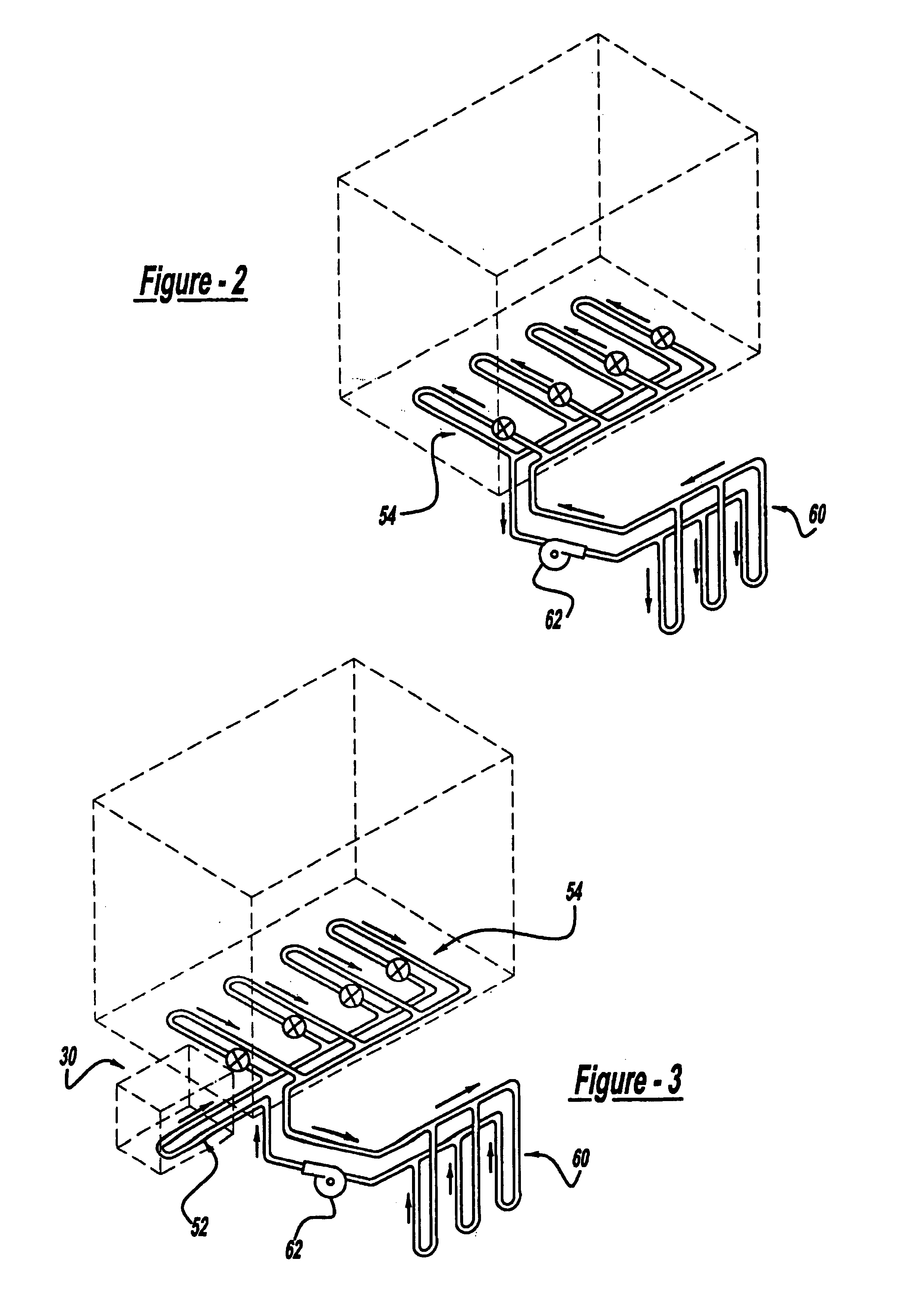
[0005]It is an object of the present invention to provide an energy transfer system which significantly reduces the energy required to maintain the fluid temperature of a circulating fluid in a piping system to prevent underfloor icing and which also reduces the energy consumption of the cooling system by lowering the condensing temperature. The present invention provides the art with an energy transfer system which utilizes the heat created by the ground, standing well, open well or body of water and the cooling system (condenser / compressor) in order to heat the fluid passed through the piping system. The present invention includes a fluid which withdraws heat from a heat exchanger in the ground prior to entering the condenser and / or compressor where a second heat exchanger also withdraws additional heat. Alternatively, water at desired temperatures can be drawn from a standing well, open well or body of water and used as the fluid. The heated fluid then passes under the floor into a piping grid to warm the space beneath the floor. Additional heating, from a source such as a gas boiler or electric heat pump, may be required to heat the fluid during periods when heat from the cooling system and ground is insufficient.
[0006]An additional objective of the present invention is to provide an energy transfer system which reduces the energy required during summer operation (or in a warm climate year round) to cool the building. This is accomplished by using the previously described ground heat exchanger or standing well, open well or body of water to reject heat from the fluid into the ground or water prior to entering the building walls and roof where heat gained from the ambient surroundings is absorbed by the fluid in the piping circuit passing through the walls and roof.

Problems solved by technology

In these facilities, it is possible that the floor, which is ordinarily concrete, may freeze.
This is known as underfloor icing which, as the ice expands, may cause heaving of the floor or columns, which hold the building together.

Method used


Image

  • Energy transfer system for cold storage facilities
  • Energy transfer system for cold storage facilities
  • Energy transfer system for cold storage facilities

Examples


Embodiment Construction

[0015]Turning to FIG. 1, an energy transfer system for a cold storage facility is illustrated and designated with the reference numeral 10. The cold storage facility 10 includes a building 12 which includes a roof 14 as well as walls 16 and a floor 18. The walls may include a door 20 which enables access into an additional storage room 22 which acts as a loading dock. The additional storage room 22 includes a door 24 which enables access to trucks which may be loaded with the frozen material inside of the cold storage building 12.

[0016]The building 12 includes a cooling system 30 which conditions the air within the building to maintain it at cold, freezing or below levels. Ordinarily, the cooling system 30 includes an evaporator 32 as well as a compressor 34 and condenser 36. The evaporator 32 is positioned within the building. The compressor 34 and condenser 36 are located outside of the building, either adjacent in a separate building or remote from the building 12. The compressor...


PUM


Abstract

A cold storage facility energy transfer system has a building which includes walls, a roof, and a floor. The building defines an enclosed space, which is to be cooled. A cooling system, which includes a compressor, a condenser, and an evaporator, is provided to cool the air within the enclosed space of the building. A ground water heat transfer mechanism reduces the operating temperature of the cooling system and raises the temperature of the building floor. A heat exchange mechanism draws heat from the compressor and the condenser to reduce operating temperature of the condenser and / or compressor. The heat exchange mechanism includes a mechanism associated with an area adjacent to the building floor for maintaining that area at a temperature so that underfloor icing is prohibited. An additional objective of the system reduces the temperature of the walls and roof of the building, reducing heat loss and improving the energy efficiency of the building.

Description

CROSS REFERENCE TO RELATED APPLICATIONS[0001]This is a continuation-in-part of U.S. patent application Ser. No. 09 / 611,141, filed Jul. 6, 2000. Now U.S. Pat. No. 6,484,794.BACKGROUND AND SUMMARY OF THE INVENTION[0002]The present invention relates to cold storage facilities and, more particularly, to energy transfer systems for maintaining the floor of a cold storage facility at a desired temperature to eliminate underfloor icing and for reducing the operating temperature of the condenser and / or compressor in the cooling system and for cooling the exterior of the building.[0003]Cold storage facilities are utilized in many different industries for storing perishable items such as meat, dairy products, vegetables or the like. Some of these applications require the temperature within the facility to remain well below zero degrees Fahrenheit such as for the storage of ice cream or ice. In these facilities, it is possible that the floor, which is ordinarily concrete, may freeze. In the ev...

Claims


Application Information

Patent Timeline
Patent Type & Authority Patents(United States)
IPC IPC(8): F25B29/00F25D13/00F25D16/00F25D21/04F25D23/00
CPCF25D13/00F25D21/04F25D23/003F25D16/00F24F2005/0057Y02B10/40Y02E60/14
Inventor SCHULAK, EDWARD R.HORVAY, J. BENJAMIN
Owner SCHULAK EDWARD R
Learn More