
Method of opening joints between drilling components, and rock drill

a technology of drilling components and opening joints, which is applied in the direction of manufacturing tools, percussive tools, portable drilling machines, etc., can solve the problems of difficult opening of drilling components joints and damage to drill holes, and achieve the effect of reducing the pressure of the pressure medium

Inactive Publication Date: 2006-04-25
SANDVIK INTELLECTUAL PROPERTY AB
View PDF27 Cites 18 Cited by
  • Summary
  • Abstract
  • Description
  • Claims
  • Application Information

AI Technical Summary

Benefits of technology

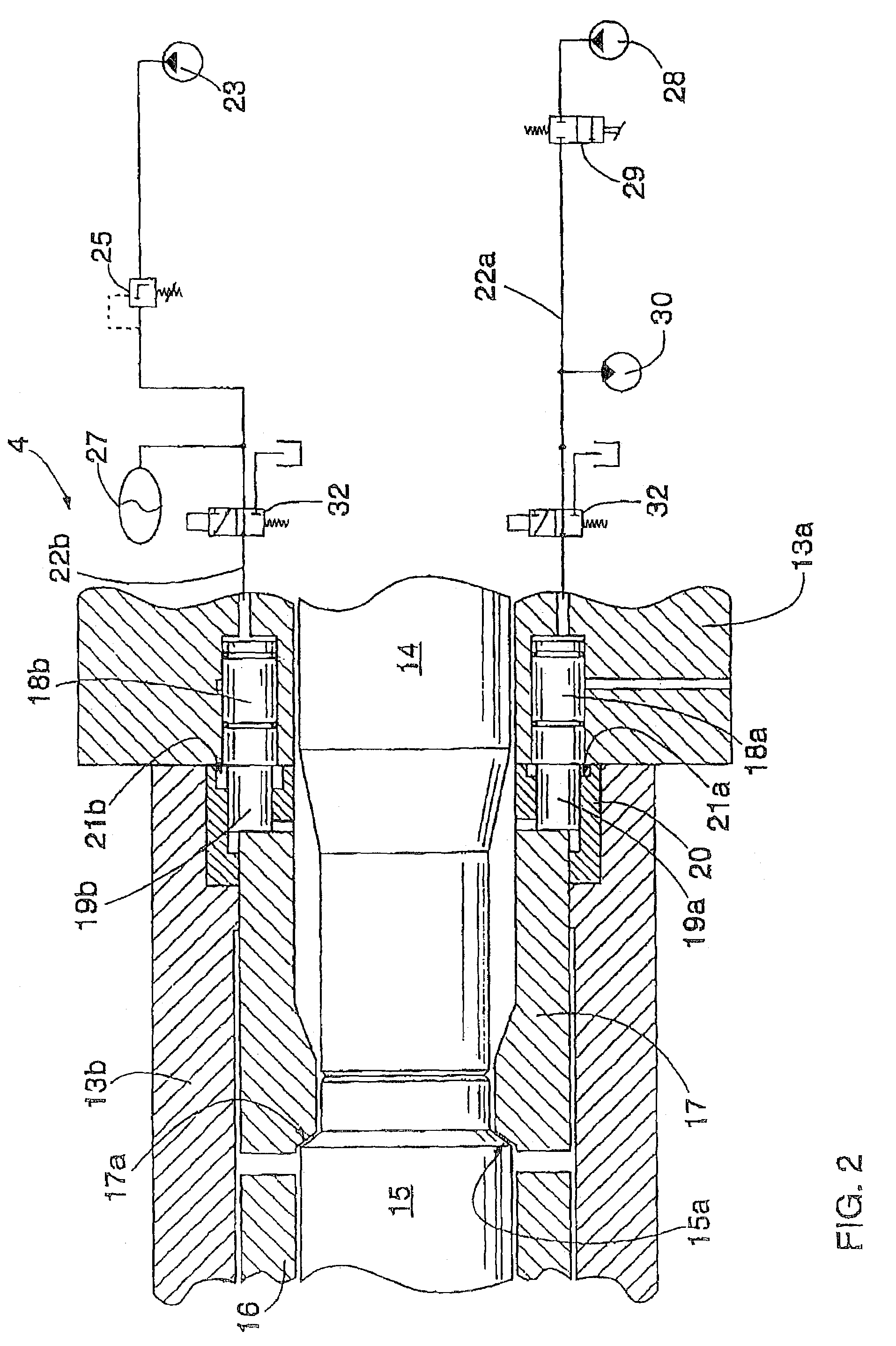
[0006]The method of the invention is characterized by reducing the pressure of the pressure medium that pushes the axial piston towards the front end of the drilling machine when drilling components are struck off so that the shank and the drilling components in its extension are substantially not supported by the axial piston in the axial direction when drilling components are struck off, the compression stress caused in the drilling components by the stroke of the percussion piston being reflected at least partially from the front end of the drilling equipment, whereby said return pulse generates tensile stress in the drilling components and their joints.

Problems solved by technology

The threaded joint is typically damaged by vibration of a loosened joint.
In the use of the drilling machine disclosed in the publication it has been noted that it is difficult to open the joints of the drilling components because as the drilling components are struck off, the axial bearing tries to ensure rock contact against the bottom of the drilling hole by supporting the shank during striking, in which case compression stress is ensured in the drilling equipment in the same way as in normal drilling.

Method used


Image

  • Method of opening joints between drilling components, and rock drill
  • Method of opening joints between drilling components, and rock drill
  • Method of opening joints between drilling components, and rock drill

Examples


Embodiment Construction

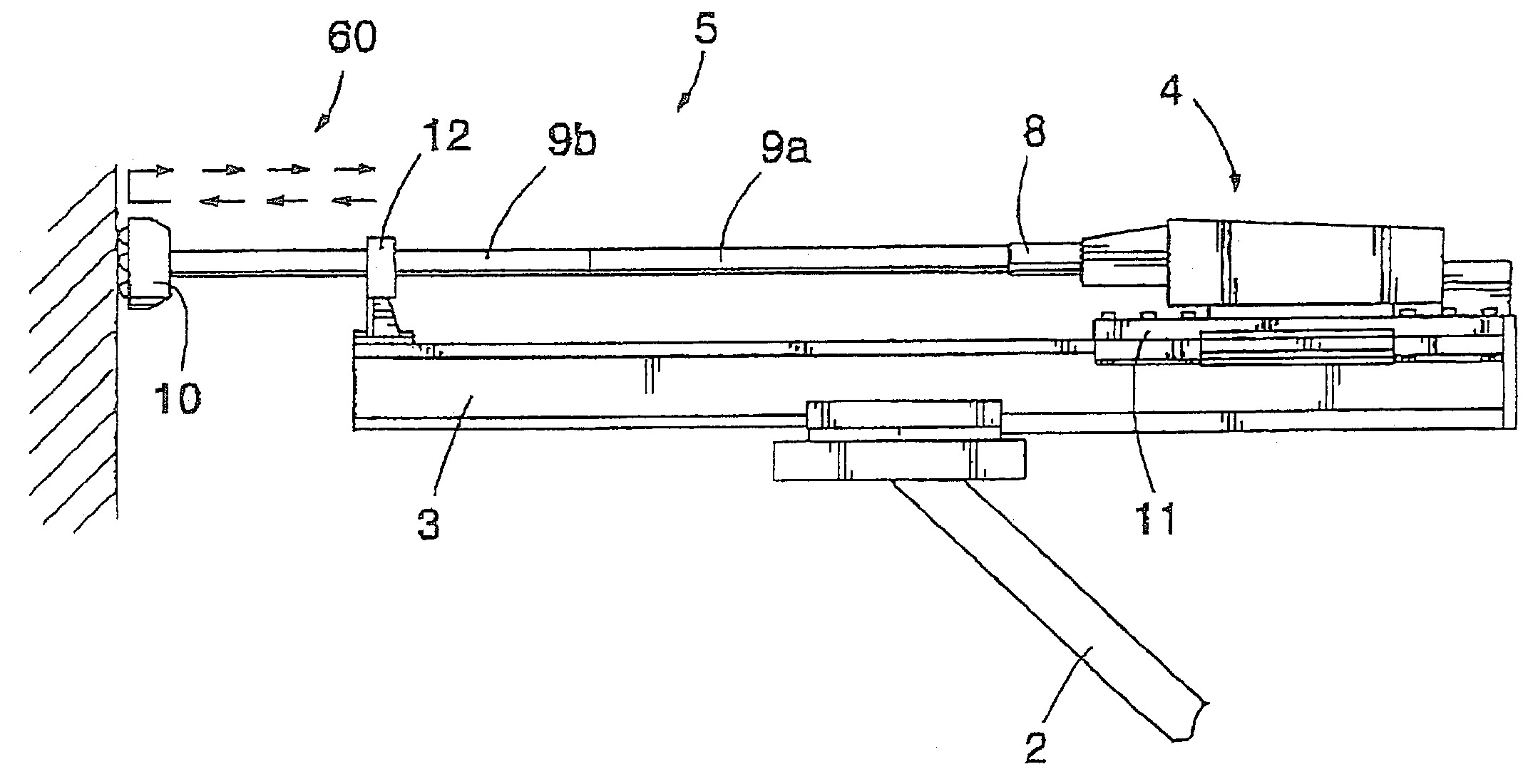
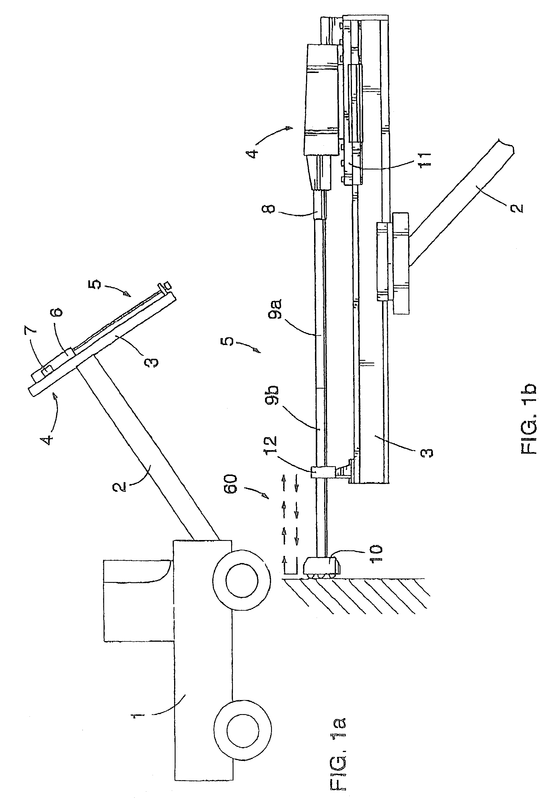
[0012]FIG. 1a is a simplified view of a rock drilling device, which comprises a movable base 1, a boom 2 and a feeding beam 3 provided at the free end of the boom. The rock drill 4 can be moved with respect to the feeding beam and the necessary drilling equipment 5 is attached to the shank of the rock drill. The rock drill comprises a percussion device 6 for striking the shank and a rotating device 7 for rotating the shank. The shank transmits the percussion force and the rotational force to the drilling equipment, which transmits them further to the rock to be drilled.

[0013]In the solution shown in FIG. 1b the drilling equipment 5 comprises a first drill rod 9a attached to the shank 8 and a second drill rod 9b attached to the extension of the shank. Furthermore, a drill bit 10 is attached to the outermost end of the drill rod string thus formed. Usually several extension rods are employed in drilling, but sometimes only one drill rod, in which case a drill bit is attached detachabl...


PUM

PropertyMeasurementUnit
Forceaaaaaaaaaa
Pressureaaaaaaaaaa
Tensile stressaaaaaaaaaa

Abstract

A rock drill includes a string of components interconnected by screw threads and connected to a shank. A percussion piston is reciprocated against the shank during a drilling operation, while a support device applies axial support to the rear of the shank, to enhance the drilling action. When the components are being unscrewed, the percussion piston is actuated to strike the rear end of the drill string, after the support device has at least partially released the axial support of the shank, to enable tensile stress to be generated in the components by the percussive impacts to facilitate unscrewing of the components.

Description

TECHNICAL BACKGROUND[0001]The invention relates to a method of opening joints between drilling components in a rock drill which is fed with respect to a feeding beam during drilling and which comprises a frame, a percussion device arranged in the frame. The conventional percussion device comprises a percussion piston which moves in the longitudinal direction, a shank which is arranged in the axial extension of the percussion piston for being struck by the percussion piston and to which the necessary drilling components, such as drill rods, a drill bit and the like are attached to form drilling equipment, and a rotating device which by means of a rotating bushing rotates the shank. The conventional rock drill further comprises at least one axial piston, which is positioned rearwardly of the shank and arranged to move in the axial direction by means of the pressure of a pressure medium fed onto its back surface during drilling, the axial piston acting on the shank by supporting it tow...

Claims


Application Information

Patent Timeline
IPC IPC(8): E21B19/16B28D1/14B28D1/26E21B1/00E21B1/26E21B7/02E21B15/04
CPCE21B7/022E21B19/16E21B7/025
Inventor MUUTTONEN, TIMOSALMINEN, PEKKA
Owner SANDVIK INTELLECTUAL PROPERTY AB
Learn More