Welding terminal and welding apparatus for welding the same

Inactive Publication Date: 2006-04-25
YAZAKI CORP
View PDF5 Cites 25 Cited by
  • Summary
  • Abstract
  • Description
  • Claims
  • Application Information

AI Technical Summary

Benefits of technology

[0014]It is therefore an object of the present invention to provide a welding terminal, as well as a welding apparatus for welding the same, in which when welding a conductor por

Problems solved by technology

Even when the welding is effected in such a condition, those portions of the conductor portion 108, facing the corner portions

Method used


Image

  • Welding terminal and welding apparatus for welding the same
  • Welding terminal and welding apparatus for welding the same
  • Welding terminal and welding apparatus for welding the same

Examples


first embodiment

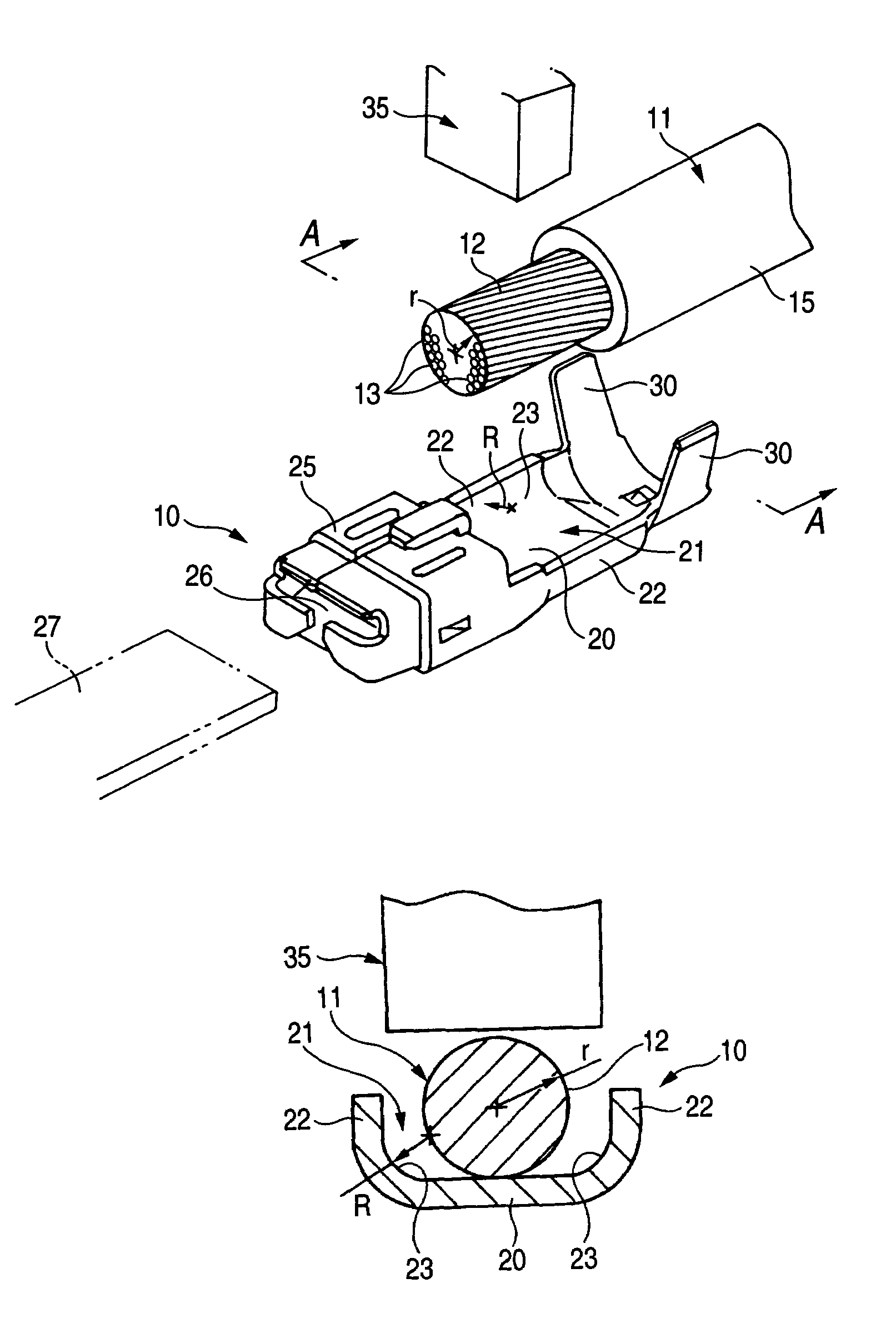
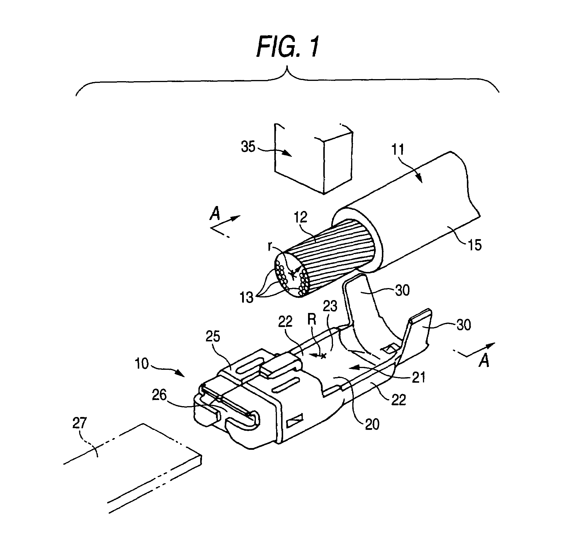
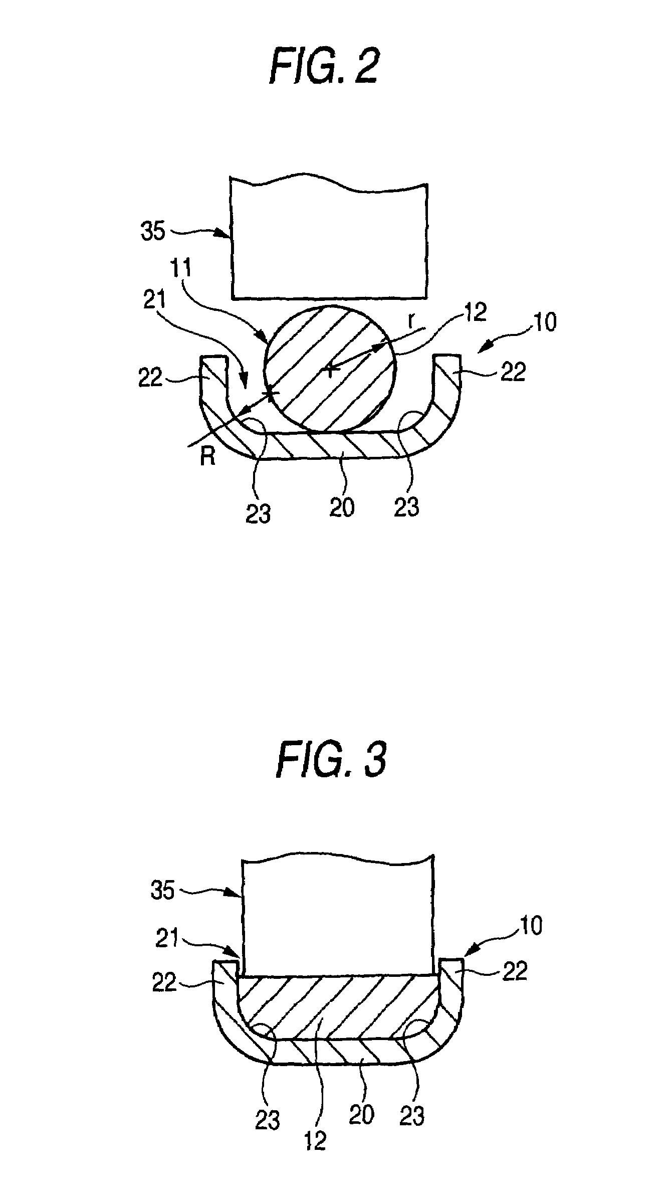
[0040]FIG. 1 is a perspective view showing an overall construction of the welding terminal according to the invention, FIG. 2 is a cross-sectional view of the welding terminal of FIG. 1 taken along the line A—A of FIG. 1, and FIG. 3 is a cross-sectional view showing a welded condition of the welding terminal shown in FIG. 2.

[0041]As shown in FIG. 1, the welding terminal 10 according to the first embodiment of the invention, has an integral construction, and is formed by bending an electrically-conductive sheet. The welding terminal 10 includes a terminal base plate portion 20 which has a female terminal portion 25 (serving as an electrical connection portion), formed at a front end portion thereof, and also has a pair of wire sheath-clamping portions 30 formed at a rear end portion thereof. Further, a pair of side walls 22 are formed on and project generally perpendicularly from opposite side edges of an intermediate portion of the terminal base plate portion 20, respectively, to fo...

second embodiment

[0060]As shown in FIG. 4, the welding apparatus 50 for the welding terminal is an ultrasonic welding apparatus including a vibration horn 51 serving as a joining and pressing member. The vibration horn 51 presses a conductor portion 12 of a wire 11, which has a plurality of conductors 13 covered with an insulating sheath 15, against a welding portion 21 of the welding terminal 10, having a pair of side walls 22 formed on and projecting generally perpendicularly respectively from opposite side edges of a terminal base plate portion 20, so as to weld the conductors to this welding portion.

[0061]A convex ridge 53 is formed on a distal end face for pressing 52 of the vibration horn 51, and has a curved face which is curved in a direction of a width of the terminal. In this embodiment, the convex ridge 53 has a cross-sectionally arcuate shape defined by a cylindrical curved face.

[0062]Next, a method of connecting the welding terminal 10 and the wire 11 together by the use of the welding...


PUM


Abstract

A welding terminal for electrically connecting a conductor portion of a wire includes a terminal base plate portion, on which the conductor portion is placed for welding and a pair of side walls, formed on opposite side edges of the terminal base plate portion so as to stand perpendicularly. The wire has a plurality of conductors covered with a insulating sheath. Each corner portion formed by the each side wall and terminal base plate portion has a rounded shape in cross section.

Description

BACKGROUND OF THE INVENTION[0001]This invention relates to a welding terminal and a welding apparatus for welding the welding terminal, and more particularly to such welding terminal and welding apparatus, in which for example, an insulating sheath of a wire is removed to thereby expose a conductor portion thereof, and this exposed conductor portion is welded to a terminal base plate portion by welding or vibration welding.[0002]A related method of connecting a welding terminal and a wire together is disclosed in JP-A-62-140308, in which a conductor portion of a wire is welded to a central portion of a welding portion of a terminal base plate by electric resistance welding, ultrasonic welding or the like, thereby enhancing the reliability of the electrical connection.[0003]For example, as shown in FIG. 6, a welding terminal 100 of an integral construction, formed by bending an electrically-conductive sheet, includes a terminal base plate portion 101 which has an earth fastening hole...

Claims


Application Information

Patent Timeline
IPC IPC(8): H01R4/02B23K20/10B23H11/00B23K9/32B23K101/38H01R4/18H01R43/02
CPCB23H11/006H01R43/0214B23K9/32H01R4/187H01R43/0207
Inventor FUJIMOTO, KEISAKAGUCHI, TADAHISA
Owner YAZAKI CORP
Why Eureka
Try Eureka