Corkscrew reinforced left ventricle to coronary artery channel

a technology of left ventricle and corkscrew, which is applied in the field of corkscrew reinforced left ventricle to coronary artery channel, can solve the problems of cyclic fatigue fracture, dislocation of the tube, and chronic inflammation response, and achieves high stability, good tolerance, and long and continuous movement.

Inactive Publication Date: 2006-04-25
HORIZON TECH FUNDING CO LLC
View PDF624 Cites 153 Cited by
  • Summary
  • Abstract
  • Description
  • Claims
  • Application Information

AI Technical Summary

Benefits of technology

[0006]What is primarily needed is a device that can control the shape of the open channel between the left ventricle and coronary artery, and can withstand long and continuous complex movement without causing irritation, dislodgement, or fracture. An alternative approach to spikes, and stents, is the use of a screw in coil. The design of such a coil would be much like that of a corkscrew. This same design has been used on implantable ...

Problems solved by technology

Both designs have to deal with problems arising from the contraction and multidimensional movements of the heart wall in relation to the device.
For a straight hollow tube the movement may create irritation between the tissue and the metal interface that may lead to a chronic inflammatory response, and maybe even to dislodgement of th...

Method used


Image

  • Corkscrew reinforced left ventricle to coronary artery channel
  • Corkscrew reinforced left ventricle to coronary artery channel

Examples


Embodiment Construction

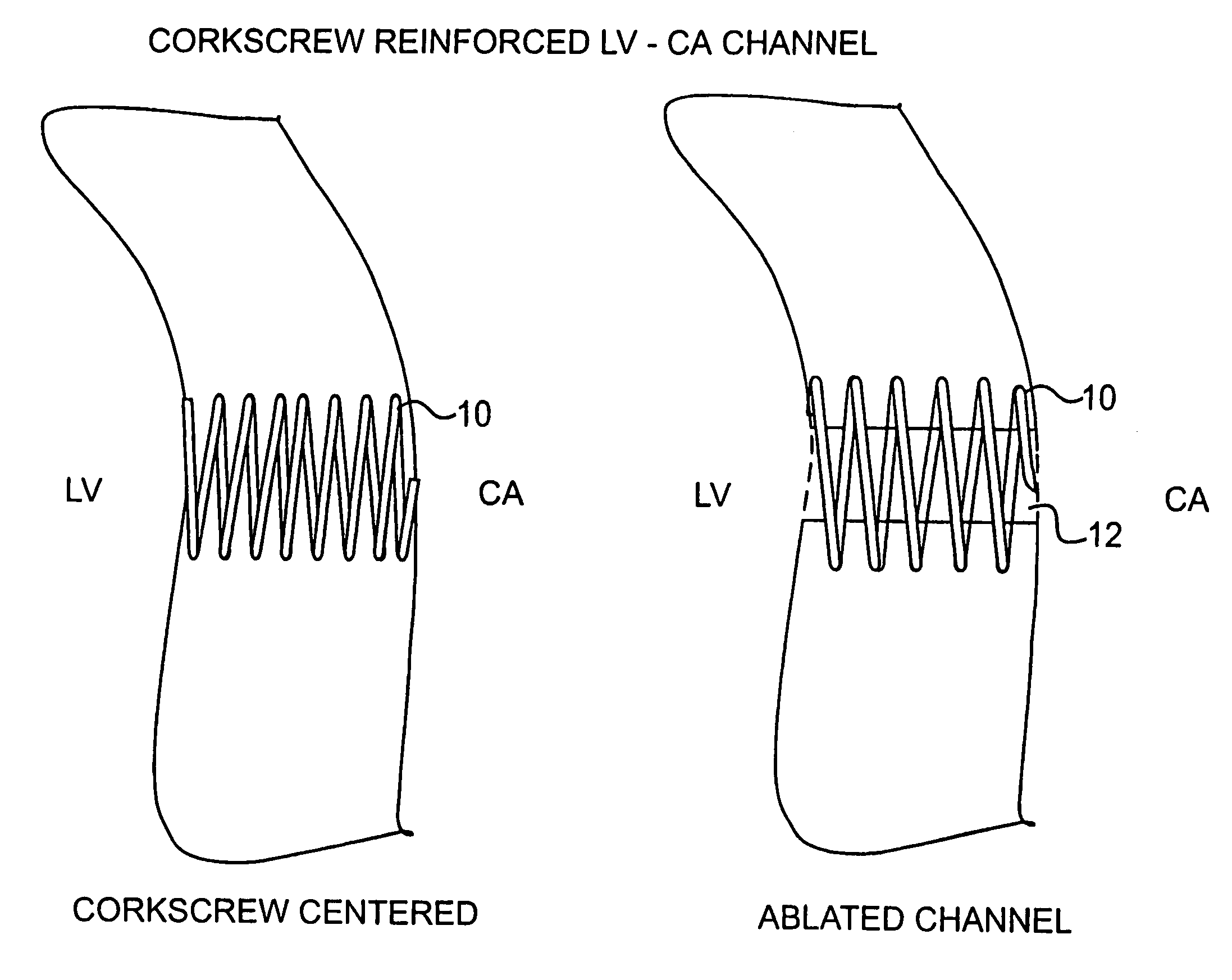
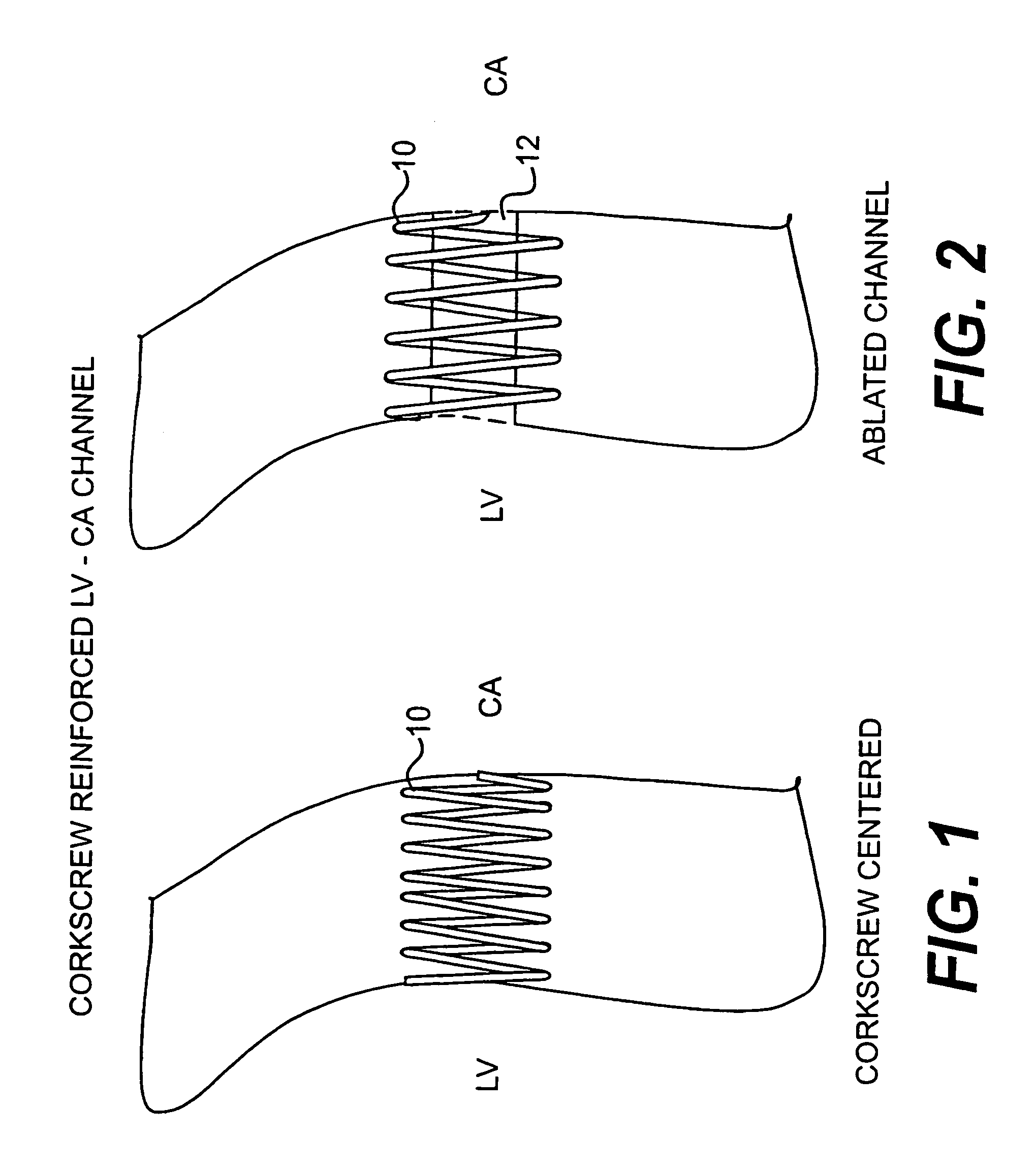
[0009]FIGS. 1 and 2 roughly show the preferred design, which would comprise first screwing in a coil 10 into the heart wall HW between the left ventricle LV and coronary artery CA (FIG. 1), and then followed by forming of a channel 12 by, for example, laser, plasma, electrical, or mechanical device (FIG. 2). At this time it would be preferred to use the plasma ablation technique as the diameter of the channel can be controlled with considerable accuracy at the dimensions one would want, and also the asymmetry can be controlled.

[0010]In one embodiment, the corkscrew or coil 10 may be configured to have a desired pitch and spacing so that insertion of the coil 10 into the heart wall does not puncture through the coronary artery CA. This is accomplished by choosing an entry point for the coil 10 adjacent the coronary artery, and screwing the coil 10 into the heart wall such that the coronary artery is positioned in between the turns of the coil as the coil is inserted. In this embodime...


PUM


Abstract

A coil is screwed into the heart wall HW between the left ventricle and coronary artery, followed by forming of a channel with laser, plasma, electrical, or mechanical device therethrough.

Description

CROSS REFERENCE TO RELATED APPLICATIONS[0001]The application is a national phase application based on PCT / US00 / 21120, filed Aug. 3, 2000, and claims the benefit of U.S. Provisional Application No. 60 / 147,210, filed Aug. 4, 1999, the content of both of which is incorporated herein by reference.BACKGROUND OF THE INVENTION[0002]1. Field of the Invention[0003]This invention relates to method and apparatus for forming a channel to allow communication of fluids from one portion of a patient's body to another, and more particularly, to a device that can communicate blood between the left ventricle and coronary arteries or veins.[0004]2. Description of the Related Art[0005]Currently there exists a shunting concept that establishes a passage from the left ventricle directly to the coronary artery by the placement of a stent or hollow tube in a channel formed therethrough. Other designs also suggested that it might be possible to have a stent-less channel (see U.S. Pat. No. 5,662,124). Both d...

Claims


Application Information

Patent Timeline
IPC IPC(8): A61B17/34
CPCA61B17/3478A61B18/24A61B2018/00392A61B2017/00252A61B2017/00247
Inventor CAHALAN, PATRICK
Owner HORIZON TECH FUNDING CO LLC
Why Eureka
Try Eureka