Gridded susceptor

a susceptor and gridded technology, applied in the field of susceptor configuration, can solve the problems of asymmetric “saddle”-shaped susceptor, damage to the backside of the wafer, and defective sections left on the wafer, so as to reduce the degree of warping, control and reduce the radical length

Active Publication Date: 2006-04-25
ASM IP HLDG BV
View PDF26 Cites 18 Cited by
  • Summary
  • Abstract
  • Description
  • Claims
  • Application Information

AI Technical Summary

Benefits of technology

[0013]In one embodiment, grids of constant surface areas are formed with reducing radical length at greater distances from the susceptor center, compensating for increasing circumferential length. Advantageously, this design tends to control and reduce the degree of wafer warping.
[0014]In another embodiment, circumferential asymmetry is provided to the grid surface areas. Accordingly, gradients are intentionally introduced upon loading a cold wafer on the hot susceptor. Advantageously, the wafer curls in a predictable fashion, reducing the randomness of the direction in which the wafer warps during processing.

Problems solved by technology

During this curl, damage to the backside of the wafer can occur through contact with the susceptor.
On the other hand, conventional gridded susceptors, with grids arranged in an X-Y checkered configuration, have been found to cause uneven dishing, which can result in an asymmetric “saddle” shaped susceptor, rather than a “dish” shape.
A saddle shaped susceptor causes damage to the backside of a wafer, leaving the wafer with defective sections.
Susceptor warping is especially damaging when processing large wafers.

Method used


Image

  • Gridded susceptor
  • Gridded susceptor
  • Gridded susceptor

Examples


Embodiment Construction

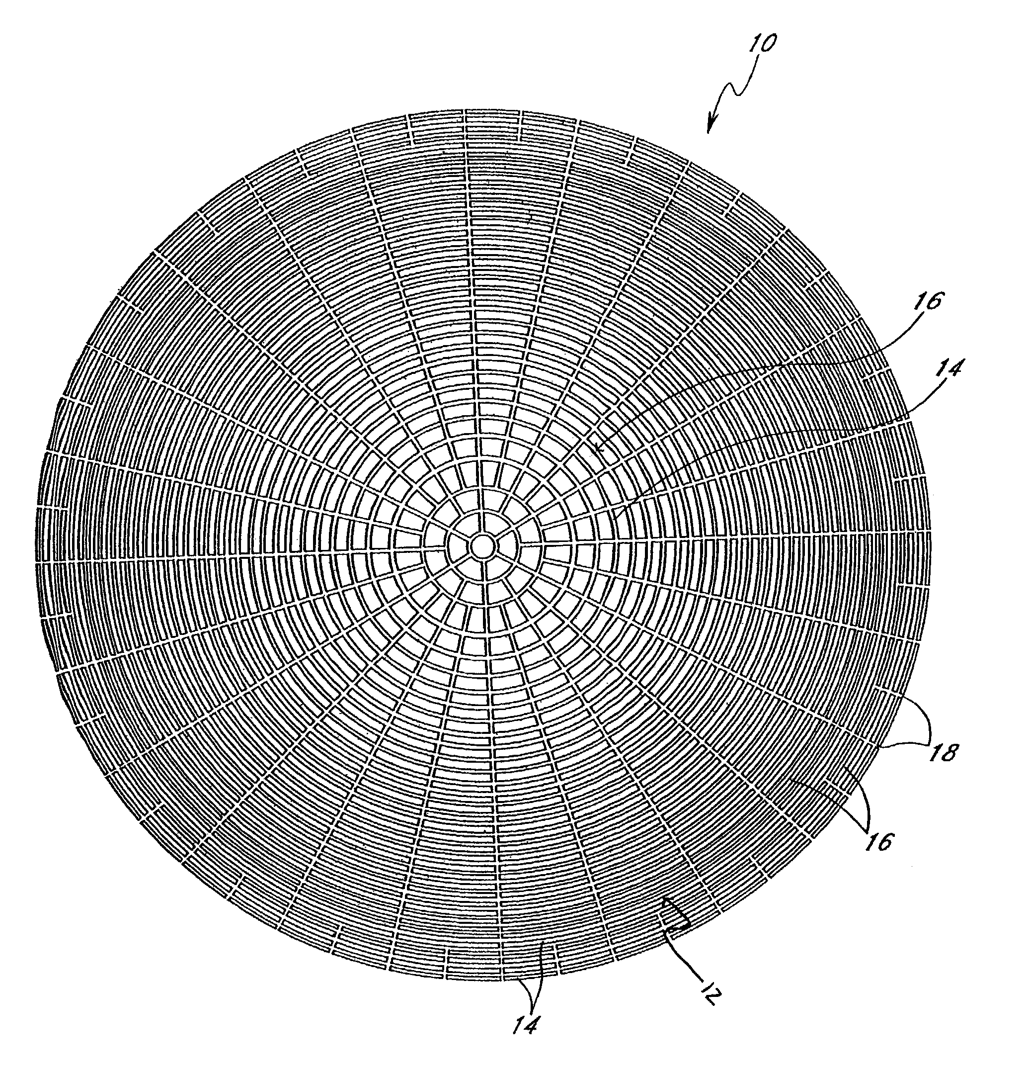
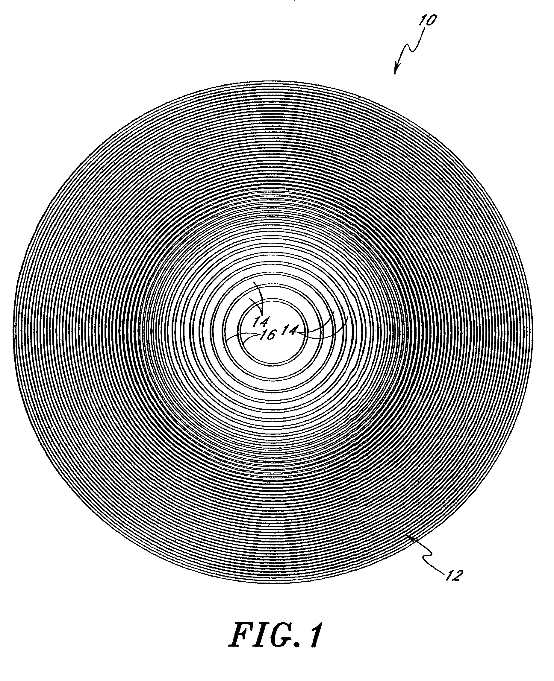
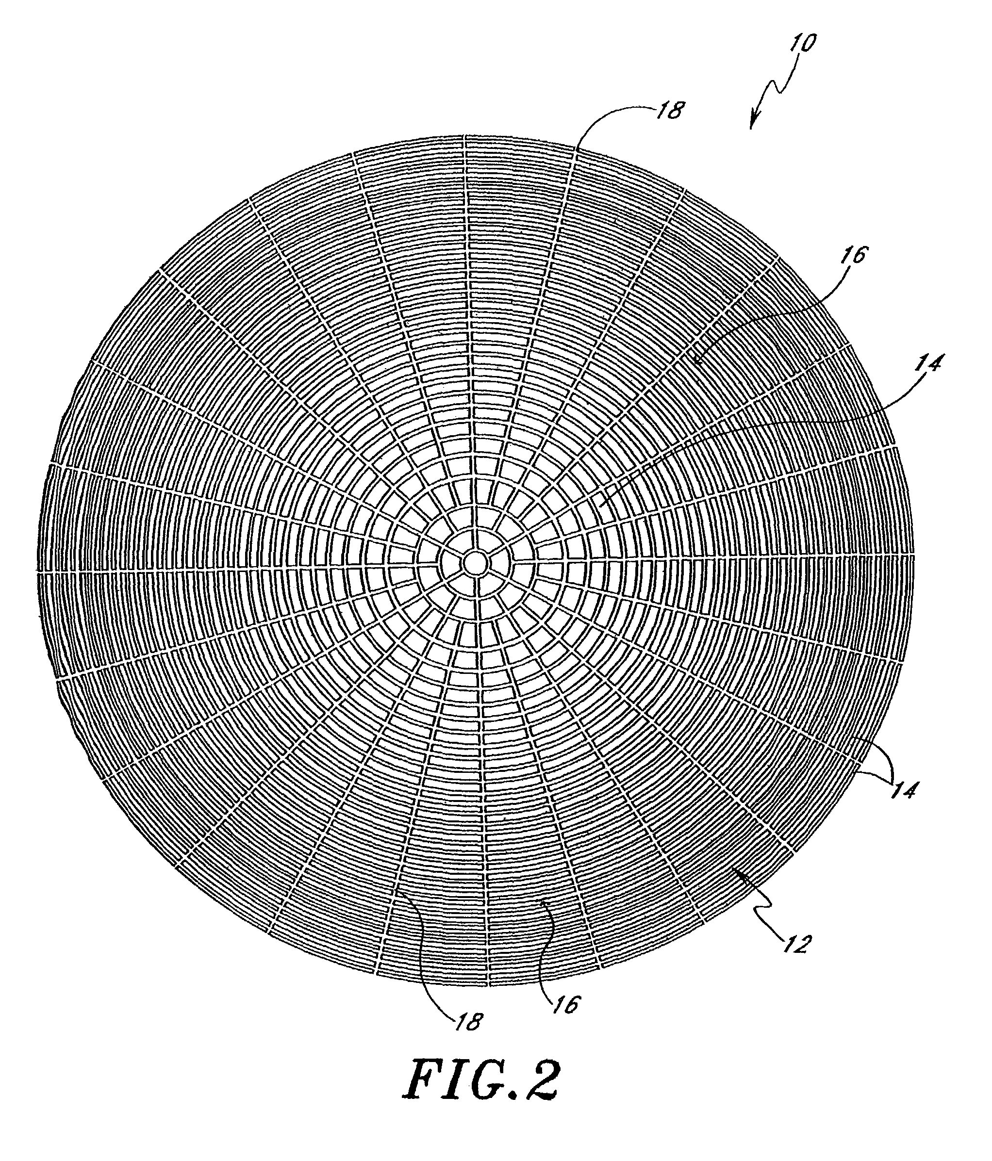
[0023]The susceptors described herein are preferably implemented in machined graphite coated with ceramic, more preferably coated with silicon carbide (SiC). The bottom or backside has a substantially reduced surface area, compared to the frontside, such that dishing can be induced by thermal processing. Preferably, the susceptors are employed in cold wall, radiantly heated semiconductor processing chambers. During processing, a wafer is placed with its backside face parallel to the top face of the susceptor.

[0024]FIGS. 1 and 2 illustrate alternative embodiments of the axisymmetric pattern of the gridded front face 12 of susceptor 10 with constant surface area grids 14. Surface areas are kept constant in both embodiments by reducing radial length at greater r positions. The embodiments are symmetrical with respect to both the θ and r direction. The symbols θ and r should be understood to have their standard geometrical definitions with r representing radial position and θ representi...


PUM

PropertyMeasurementUnit
surface areaaaaaaaaaaa
radial distanceaaaaaaaaaa
radial lengthaaaaaaaaaa

Abstract

Susceptor designs are provided for controlling damage to wafers, particularly during cold wafer drops-off on a hot susceptor. The designs include axisymmetric grid designs, such that thermal gradients are symmetrical in the circumferential (θ) direction and the same traversing any particular radial line. The grids are preferably arcuate and each have the same surface area. In one embodiment an outer zone is asymmetrically designed to induce predictable wafer curling in a saddle shape.

Description

REFERENCE TO RELATED APPLICATION[0001]This application claims the priority benefit under 35 U.S.C. §119(e) of provisional application No. 60 / 343,979, filed Dec. 27, 2001.FIELD OF THE INVENTION[0002]The invention relates generally to susceptors for supporting semiconductor substrates in process chambers, and more particularly, to susceptor configurations for tailored thermal effects.BACKGROUND OF THE INVENTION[0003]Semiconductor fabrication processes are typically conducted with the substrates supported within a chamber under controlled conditions. For many processes, semiconductor substrates (e.g., silicon wafers) are heated inside the process chamber. For example, substrates can be heated by direct physical contact with an internally heated wafer holder or “chuck.”“Susceptors” are wafer supports used in radiantly heated system where the wafer and susceptor absorb radiant heat.[0004]Susceptors are commonly formed by machining graphite into a desired shape and applying silicon carbid...

Claims


Application Information

Patent Timeline
Patent Type & Authority Patents(United States)
IPC IPC(8): H01L21/00C23C16/00
CPCH01L21/67103Y10T279/23Y10T279/11
Inventor KEETON, TONY J.LUTZ, ZACHARY L.
Owner ASM IP HLDG BV
Why Eureka
Try Eureka