
Thermal transfer sheet

a transfer sheet and transfer recording medium technology, applied in the direction of thermography, instruments, transportation and packaging, etc., can solve the problems of poor fastness or resistance properties of formed images, disadvantageous poor fastness and resistance properties such as lightfastness and weathering resistance, and achieve excellent various fastness or resistance properties. good transferability

Inactive Publication Date: 2006-04-25
DAI NIPPON PRINTING CO LTD
View PDF5 Cites 9 Cited by
  • Summary
  • Abstract
  • Description
  • Claims
  • Application Information

AI Technical Summary

Benefits of technology

The present invention provides a thermal transfer sheet that can yield thermally transferred images with excellent fastness and resistance properties even under severe service conditions. The sheet includes a thermally transferable protective layer that can be transferred onto an object with good transferability. The protective layer has a scratch-resistant layer that can prevent deformation of the object and an adhesive layer for easy separation from the substrate sheet. The thermal transfer sheet can be used as an intermediate transfer recording medium with a peel layer, a cured product of an ionizing radiation-curable resin layer, and a receptive layer. The ionizing radiation-curable resin used in the invention is a urethane-modified acrylic base resin that has excellent resistance properties. The invention also provides a method for forming the thermal transfer sheet and the intermediate transfer recording medium.

Problems solved by technology

The thermal ink transfer method, however, is unsuitable for the formation of images required to have high quality, such as a photograph of a face.
Further, the formed images are disadvantageously poor in fastness or resistance properties, particularly abrasion resistance.
Unlike images formed using printing ink, the images formed by thermal dye sublimation transfer, however, do not contain any vehicle and thus are disadvantageously poor in fastness and resistance properties such as lightfastness and weathering resistance.
This method, however, involves a complicate operation.
In addition, in this method, since lamination is carried out on the whole object, curling occurs in the object.
Further, a very thin film cannot be used for reasons of laminating operation.
This inevitably increases the thickness of the whole print.
The fastness and resistance properties of the thermally transferred image, however, are not yet satisfactory under severe practical service conditions.
The protective layer transfer sheet is advantageous in that the size of the protective layer (resin layer) transferred can be properly varied, but on the other hand, a tendency toward an increase in protective layer transfer processing speed has made it difficult to transfer the protective layer with good transferability.
The protective layer transfer sheet has many additional disadvantages including that, when the fastness or resistance properties of the protective layer, such as heat resistance is improved, heat applied at the time of the transfer of the protective layer is likely to deteriorate the transferability.
However, the hardness of the ionizing radiation-cured resin layer is so hard that the ionizing radiation-cured resin layer cannot conform to the flexibility of the object, leading to the deformation of the object between the transfer portion and the non-transfer portion of the intermediate transfer recording medium.
Further, in transferring the intermediate transfer recording medium onto an object, due to a tendency toward an increase in transfer processing speed, the transferability of the intermediate transfer recording medium is unsatisfactory, and, in this case, for example, uneven edge of the transferred portion or uneven transferred portion, which is disadvantageous from the practical point of view, occurs.

Method used


Image

  • Thermal transfer sheet
  • Thermal transfer sheet
  • Thermal transfer sheet

Examples


example 1a

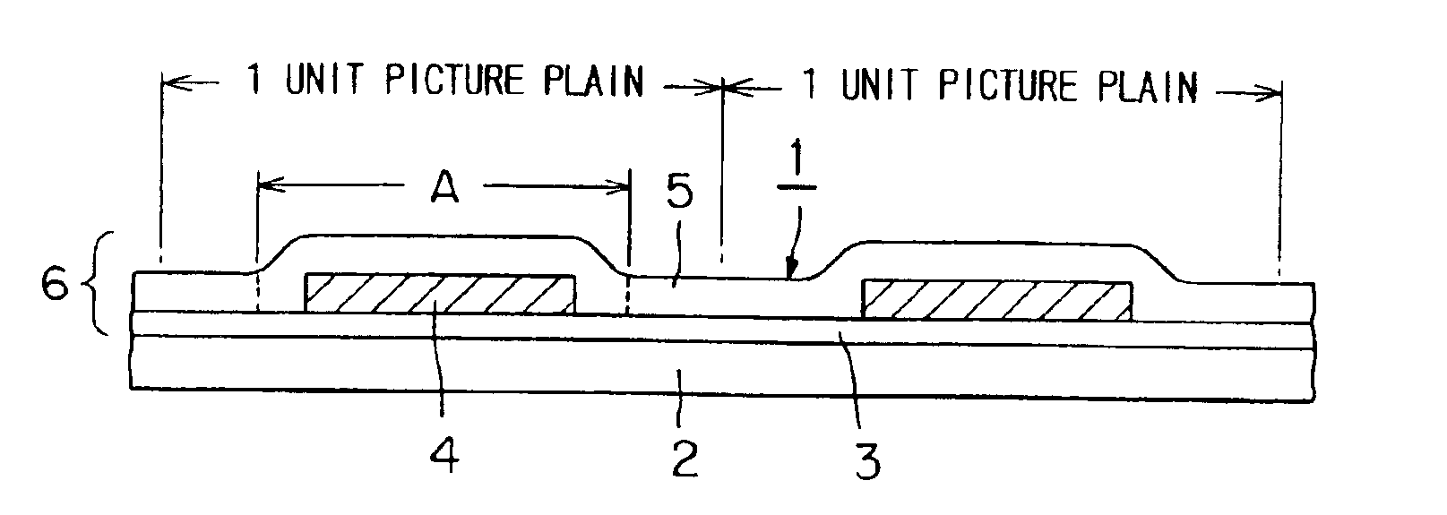
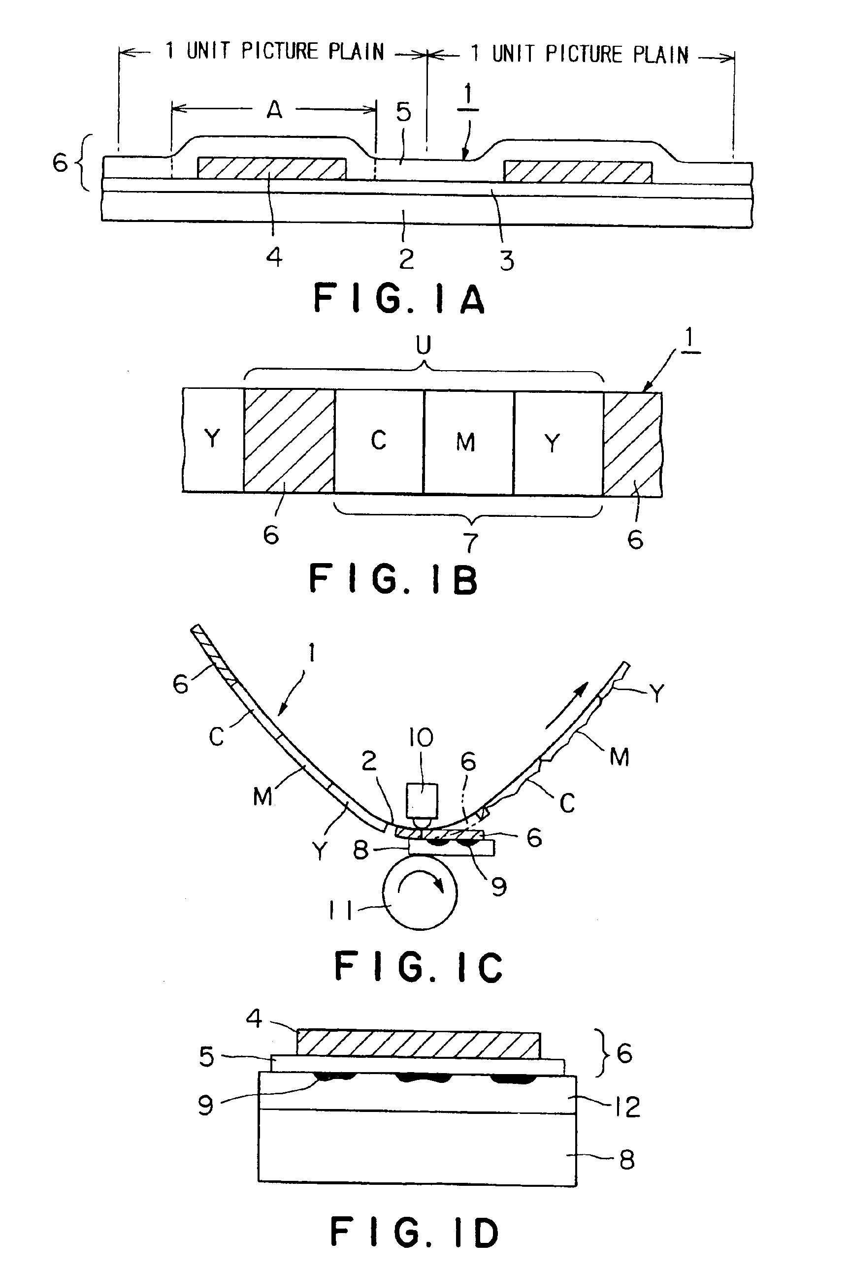
[0127]A 12 μm-thick polyethylene terephthalate film (Lumirror, manufactured by Toray Industries, Inc.) was provided as a substrate sheet. A coating liquid for a peel layer having the following composition was gravure coated on one side of the substrate sheet to form a peel layer at a coverage of 1.0 g / m2 on a dry basis. A coating liquid for a scratch-resistant layer having the following composition was gravure coated on the peel layer for each picture plane unit as shown in FIG. 1A to form a scratch-resistant layer at a coverage of 4.0 g / m2 on a dry basis. Further, as shown in FIG. 1A, a coating liquid for an adhesive layer having the following composition was gravure coated on the scratch-resistant layer and the peel layer to form an adhesive layer at a coverage of 1.0 g / m2 on a dry basis. Thus, a thermal transfer sheet of Example 1A was prepared.

[0128]After coating of each layer in the thermal transfer sheet, the coating was dried by conventional hot-air drying. In the case of the...

example 1b

[0131]A thermally transferable protective layer having a layer construction of peel layer / scratch-resistant layer / adhesive layer, which is the same layer construction as adopted in Example 1A, was formed on the same substrate sheet as used in the thermal transfer sheet prepared in Example 1A as shown in FIG. 1B. In this case, it is a matter of course that, regarding the coating area of each layer in the thermally transferable protective layer, the scratch-resistant layer was formed in a smaller area than the area of each of the peel layer and the adhesive layer. The area of the scratch-resistant layer is smaller than the area of an object in its transfer surface. Further, as shown in FIG. 1B, standard dye layers for a VDS card printer CP 510 were provided as thermally transferable colorant layers of yellow, magenta, and cyan. Thus, a thermal transfer sheet of Example 1B was prepared.

Comparative Example 1A

[0132]A thermal transfer sheet of Comparative Example 1A was prepared in the sa...

example 2a

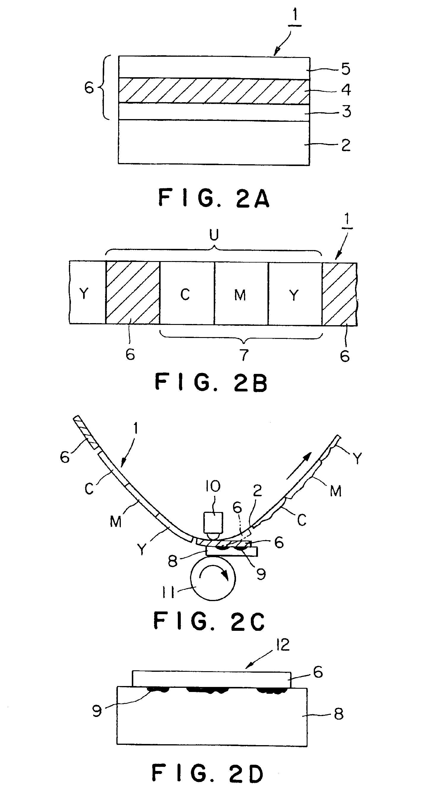
[0141]A 12 μm-thick polyethylene terephthalate film (Lumirror, manufactured by Toray Industries, Inc.) was provided as a substrate sheet. A coating liquid for a peel layer having the following composition was gravure coated on one side of the substrate sheet to form a peel layer at a coverage of 1.0 g / m2 on a dry basis. A coating liquid for a thermal transfer resin layer having the following composition was gravure coated on the peel layer to form a thermal transfer resin layer at a coverage of 4.0 g / m2 on a dry basis. Further, a coating liquid for an adhesive layer having the following composition was gravure coated on the thermal transfer resin layer to form an adhesive layer at a coverage of 1.0 g / m2 on a dry basis. Thus, a thermal transfer sheet of Example 2A was prepared.

[0142]After coating of each layer in the thermal transfer sheet, the coating was dried by conventional hot-air drying. In the case of the thermal transfer resin layer, however, after coating, the coating was dr...


PUM

PropertyMeasurementUnit
thicknessaaaaaaaaaa
thicknessaaaaaaaaaa
glass transition temperatureaaaaaaaaaa

Abstract

A thermal transfer sheet is provided that can yield thermally transferred images, which possess excellent various fastness or resistance properties even under severe service conditions, and comprises a transferable protective layer having good transferability. In a thermal transfer sheet comprising a substrate sheet and a thermally transferable protective layer on the substrate sheet, the thermally transferable protective layer comprises a scratch-resistant layer which is repeatedly provided one by one for each picture plane unit in the thermal transfer sheet. An area of the scratch-resistant layer for each picture plane unit is smaller than an area of an object in its transfer surface. By virtue of this construction, at the time of the transfer of a protective layer onto an object, layer cutting does not occur within the scratch-resistant layer but within other layer (such as peel layer or adhesive layer), and, consequently, the protective layer can be transferred with good transferability.

Description

[0001]This application is a division of U.S. Ser. No. 10 / 163,874, filed Jun. 7, 2002, now U.S. Pat. No. 6,815,397.BACKGROUND OF THE INVENTION[0002]1. Technical Field[0003]The present invention relates to a thermal transfer sheet and an intermediate transfer recording medium that can yield prints having thermally transferred images, which possess excellent various fastness or resistance properties even under severe service conditions, and can realize the transfer of a transfer portion or a protective layer onto an object with good transferability.[0004]2. Prior Art[0005]Thermal transfer has become extensively used as a simple printing method. The thermal transfer is a method which comprises the steps of: putting a thermal transfer sheet, comprising a colorant layer provided on one side of a substrate sheet, on top of a thermal transfer image-receiving sheet optionally provided with an image-receptive layer; and image-wise heating the backside of the thermal transfer sheet by heating ...

Claims


Application Information

Patent Timeline
Patent Type & Authority Patents(United States)
IPC IPC(8): B41M5/40B32B7/06B32B27/06B41M7/00
CPCB32B7/06B41M7/0027B32B27/06Y10T428/24802B32B2307/584B32B27/308
Inventor ISHIDA, TADAHIROOSHIMA, KATSUYUKIODAMURA, KOZOIMAI, TAKAYUKITAKASAKI, ETSUO
Owner DAI NIPPON PRINTING CO LTD
Learn More