
Continuous crystallization process

a continuous crystallization and process technology, applied in the field of continuous crystallization process, can solve the problems that the quality of obtained crystals remains unaffected at all, and achieve the effect of reducing the heat duty to be removed, and reducing the total amount of heat duty required

Inactive Publication Date: 2006-04-25
MITSUBISHI CHEM CORP
View PDF9 Cites 0 Cited by
  • Summary
  • Abstract
  • Description
  • Claims
  • Application Information

AI Technical Summary

Benefits of technology

Significantly reduces the heat duty required for cooling and minimizes scale formation on heat transferring surfaces, extending the operational stability of the crystallizer by controlling the degree of supersaturation and temperature variance.

Problems solved by technology

Of course, the obtained crystals remain unaffected at all in their quality even when the mother liquor is circulated to the crystallization material preparation tank without circulating it to the crystallizer.

Method used


Image

  • Continuous crystallization process
  • Continuous crystallization process

Examples


example 1

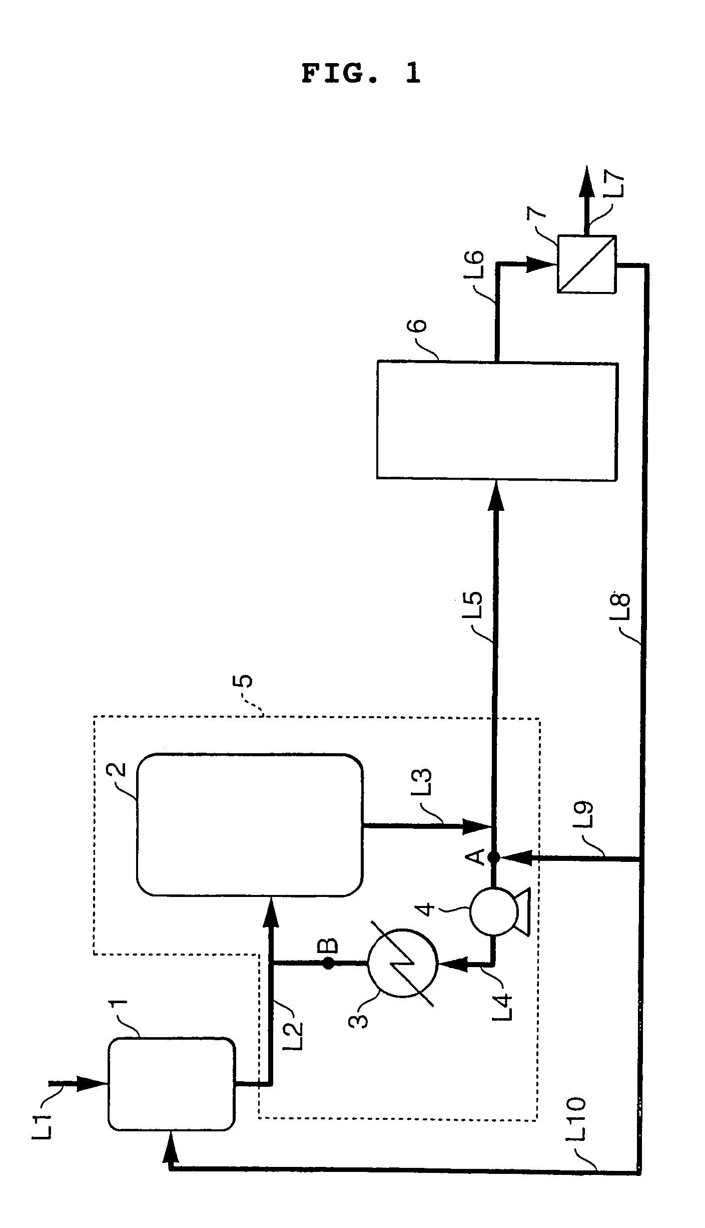
[0034]Continuous adduct crystallization was carried out according to the process flow sheet shown in FIG. 1. In the drawing, reference numeral 1 designates a crystallization material preparation tank, 2 a crystallization tank, 3 a cooler, and 4 a circulation pump. In the equipment, the section embracing the discharge line from crystallization material preparation tank 1, crystallization tank 2, cooler 3, circulation pump and the lines connecting them (the section defined by the broken line in FIG. 1) is called the first crystallization system 5, to which a second crystallization system 6 having the same makeup as the first one 5 is connected in series. The discharge rate from circulation pump 4 was adjusted to be 800 parts by weight per minute.

[0035]Dissolution of the crystals and recrystallization were conducted using 21 parts by weight / min of the cakes of the adduct mother liquor-containing material (BPA content: 50% by weight; temperature: 50° C.) and 31 parts by weight / min of a ...

example 2

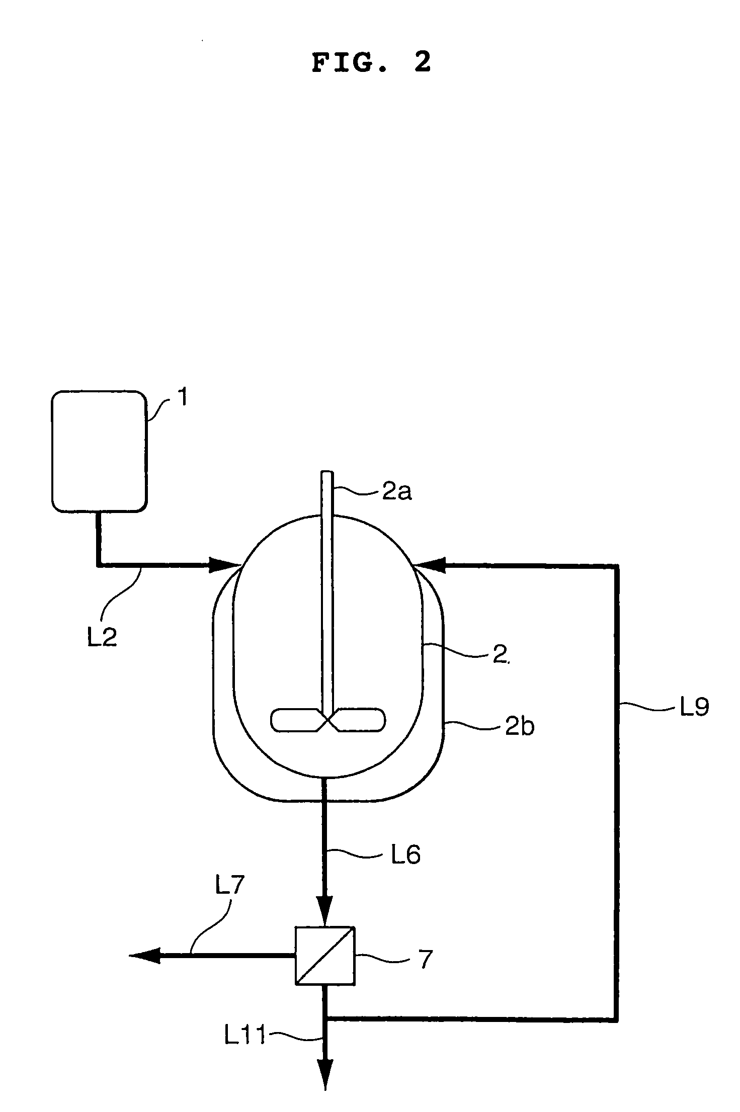
[0053]Continuous crystallization of BPA was carried out according to the process flow sheet shown in FIG. 2 wherein reference numeral 2a designates an agitator and 2b a jacket.

[0054]A composition comprising 13.2% by weight of PL, 83.4% by weight of BPA, 1.7% by weight of water and 1.7% by weight of acetone was prepared in material preparation tank 1. This tank was maintained at the precipitation temperature of BPA plus 3° C., i.e. at 132° C. The prepared precipitation material was perfectly liquid. It was discharged from tank 1 at a rate of 7.2 parts by weight per minute and continuously supplied to the liquid level of crystallization tank 2 through crystallization material supply line L2.

[0055]The flow rate of the coolant to the outer jacket (2b) was controlled so that the outlet temperature of crystallization tank 2 would be maintained at 98° C. The BPA crystals were precipitated in crystallization tank 2, and the formed slurry was continuously supplied to solid / liquid separator 7...


PUM

PropertyMeasurementUnit
outlet temperatureaaaaaaaaaa
temperatureaaaaaaaaaa
saturation temperatureaaaaaaaaaa

Abstract

A continuous crystallization process comprising the steps of supplying a crystallization material containing bisphenol A to a crystallizer to form crystals of an adduct of bisphenol A and phenol or crystals of bisphenol A, subjecting the slurry discharged from the crystallizer to solid / liquid separation, and recovering the crystals, wherein part of the mother liquor is circulated to the crystallizer. According to this process, the heat duty to be removed is reduced, deposition of solids on the inner surfaces of the crystallizer, particularly on the heat transferring surface of the cooler is restrained, and consequently the continuous operating time of the apparatus is prolonged.

Description

[0001]This is a continuation application of International Application PCT / JP2003 / 12076 filed Sep. 22, 2003. The entire content of this application is incorporated herein by reference.TECHNICAL FIELD[0002]The present invention relates to an improved continuous crystallization process. More particularly, it relates to an improved process for continuously forming the crystals of bisphenol A and phenol adducts or the crystals of bisphenol A.BACKGROUND ART[0003]It is known to produce bisphenol A by reacting an excess amount of phenol with acetone in the presence of an acid catalyst. As the method for obtaining high-purity bisphenol A from the above reaction product, a method is known in which the reaction product is subjected to a crystallization treatment to precipitate the crystals of an adduct of bisphenol A and phenol (hereinafter referred to as “adduct crystals”), then a slurry of the obtained crystals is subjected to solid / liquid separation, and the phenol is removed from the recov...

Claims


Application Information

Patent Timeline
Patent Type & Authority Patents(United States)
IPC IPC(8): C07C37/68B01D9/02C07C37/84C07C39/16
CPCC07C39/16C07C37/84
Inventor KOGA, YOSHIOKIMURA, HIROAKI
Owner MITSUBISHI CHEM CORP
Learn More