Optical pulse duration extender

a technology of optical pulses and extenders, which is applied in the direction of printers, instruments, active medium materials, etc., can solve the problems of increasing the source power required to accommodate the extenders, reducing the operation cost of the apparatus, and vanishing and useless energy of replica pulses

Active Publication Date: 2006-04-25
COHERENT GMBH
View PDF18 Cites 34 Cited by
  • Summary
  • Abstract
  • Description
  • Claims
  • Application Information

AI Technical Summary

Problems solved by technology

Accordingly, the operating cost of the apparatus is strongly dependent, among other factors, on the rate at which this degradation progresses.
In practice, however, the energy of replica pulses becomes vanishingly and uselessly small after as few as three replica pulses have been produced.
This further extension, however, would be achieved at the expense of further loss of pulse energy and an increase in source power required to accommodate the extenders.
Optical losses are due primarily to losses on each reflection from a mirror.

Method used


Image

  • Optical pulse duration extender
  • Optical pulse duration extender
  • Optical pulse duration extender

Examples


embodiment 78

[0048]FIG. 10 schematically illustrates a second preferred embodiment 78 of a pulse extender in accordance with the present invention including a delay loop 80. Pulse extender 78 is similar to extender 58 of FIG. 4 with an exception that graded reflectivity beamsplitter 62 of pulse extender 58 is replaced by a graded reflectivity beamsplitter 65 in the form of a meniscus lens having zero dioptric power. Graded reflectivity zones are formed on concave surface 67 of the beamsplitter. Surface 67, considered as a mirror, has the same focal length f as mirrors 64, 66, and 68. Opposing mirrors are spaced by a distance of about 2f such that 1:1 relay imaging conditions are satisfied. Providing that graded reflectivity beamsplitter 65 is a meniscus lens of zero power avoids the beamsplitter changing the divergence of transmitted replica pulses. It should be noted here that the sequence of graded reflectivity zones R1, R2, R3, and R4 (not shown), of beamsplitter 65 must be arranged in the op...

embodiment 86

[0049]Referring next to FIG. 11, a third preferred embodiment 86 in accordance with the present invention includes a delay loop 88 formed from a spherical graded reflectivity beamsplitter 65 in the form of a zero power meniscus and having graded reflectivity zones R1, R2, R3, and R4 (not shown) on spherical concave surface 67 thereof, a concave spherical mirror 90, and a plane mirror 92. Surface 67 of graded reflectivity beamsplitter 65 and mirror 90 are arranged confocally. Plane mirror M3 is aligned to cause a circulating beam 70 to make round trips such that the beam is progressively displaced laterally on the beamsplitter surface 67 by the width of the beam, as in other above-described embodiments. Four replica pulses 70A–D are temporally spaced apart by the round trip time of beam 70 in delay loop 88. The zero power meniscus form of graded reflectivity beamsplitter 65 provides that the divergence of the replica pulses is unchanged. Again, it is preferable that provide a one to ...

embodiment 58

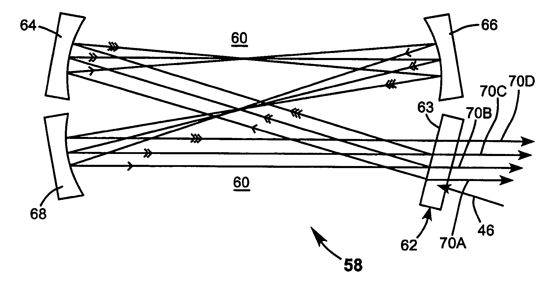
[0055]FIG. 13 schematically illustrates, in block diagram form, a preferred arrangement 110 for using the inventive pulse extender in conjunction with an excimer laser 112 and projection optics 114, for example, projection optics of optical lithography apparatus such as a step and repeat projector (stepper) or the like. The arrangement, however, is applicable to any other pulsed laser providing pulses having comparable parameters and to any other optical apparatus. Excimer laser 112, here, provides an input pulse (beam)46 that is to be broadened by an optical pulse extender in accordance with the present invention. In the arrangement of FIG. 13, the pulse extender is designated as being embodiment 58 of FIG. 3 but could be any other embodiment of the inventive pulse extender. The excimer laser and the extender would usually be assembled as a system as indicated by dashed rectangle 115. The output of the pulse extender, as discussed above, comprises temporally and spatially separated...


PUM


Abstract

An optical pulse extender includes a delay loop formed by a plurality of mirrors and a graded reflectivity beamsplitter. The mirrors and the beamsplitter are configured and aligned such that a pulse to be broadened makes a predetermined number of round trips in the delay loop and is incident on a different zone of the beamsplitter after each round trip. The different zones of the beamsplitter have different reflection values and different transmission values. These values are selected such that the pulse extender delivers a plurality of temporally and spatially separated replica pulses each thereof having about the same energy. The delivered replica pulses together provide an extended pulse having a longer duration than the input pulse. The replica pulses may be passed through a beam homogenizer to spatially homogenize the temporal characteristics of the extended pulse.

Description

TECHNICAL FIELD OF THE INVENTION[0001]The present invention relates generally to optical lithography apparatus employing pulsed ultraviolet (UV) radiation. The invention relates in particular to a pulse duration extender (pulse extender) for use with such apparatus.DISCUSSION OF BACKGROUND ART[0002]In optical lithography apparatus employing pulsed ultraviolet (UV) radiation, optical projection elements of the apparatus, commonly made from fused silica, usually progressively degrade as a result of interaction with the UV radiation being projected. The degradation is a result of multiphoton effects. Accordingly, the operating cost of the apparatus is strongly dependent, among other factors, on the rate at which this degradation progresses. The degradation rate of the optical elements depends, among other factors, on the peak intensity of ultraviolet radiation pulses incident thereon. Ultraviolet radiation pulses are typically delivered to the projection apparatus by a laser such as an...

Claims


Application Information

Patent Timeline
Patent Type & Authority Patents(United States)
IPC IPC(8): G02B27/10G03B27/52H01S3/10H01S3/22G01S13/00G02B27/14H01S3/00
CPCG02B27/106H01S3/0057G02B27/143
Inventor GOVORKOV, SERGEI V.SPINELLI, LUIS A.WHITE, WILLIAM EUGENEREED, MURRAY KEITH
Owner COHERENT GMBH
Why Eureka
Try Eureka