Imaging lens

a technology of imaging lens and focusing lens, which is applied in the field of imaging lens, can solve the problems of not providing a sufficient field angle (i.e. field of view), and achieve the effect of bright image and large field angl

Active Publication Date: 2006-04-25
FUJI PHOTO OPTICAL CO LTD
View PDF33 Cites 15 Cited by
  • Summary
  • Abstract
  • Description
  • Claims
  • Application Information

AI Technical Summary

Benefits of technology

[0006]The present invention relates to an imaging lens for forming an image of an object on an image pickup element, and relates particularly to an imaging lens for providing an image in a portable terminal device, such as a portable telephone, or in a small digital camera, or a similar device, that is compact, has a large field angle, and that provides a bright image.

Problems solved by technology

However, the imaging lenses of Japanese Laid-Open Patent Application H06-067089 have a half-field angle as small as 18.4° which thus does not provide a sufficient field angle (i.e. field of view).

Method used


Image

  • Imaging lens
  • Imaging lens
  • Imaging lens

Examples


embodiment 1

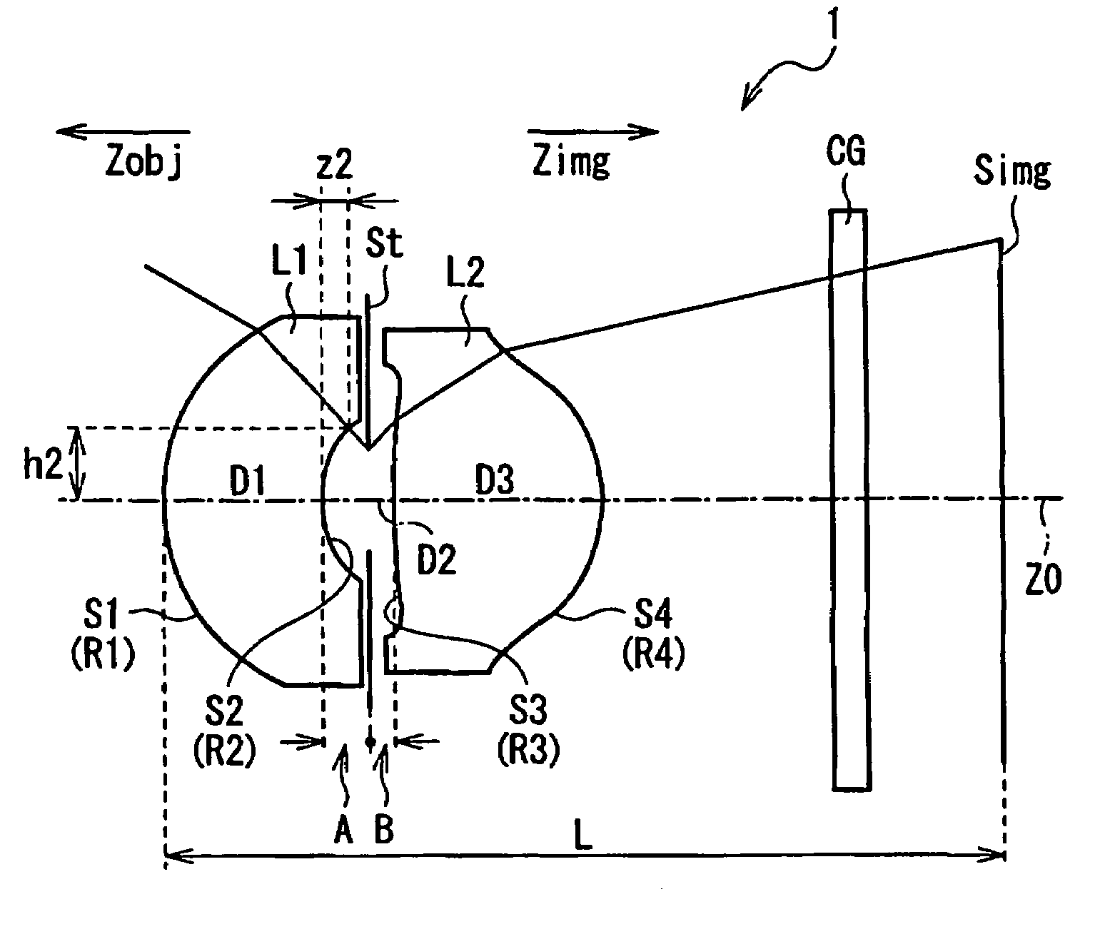
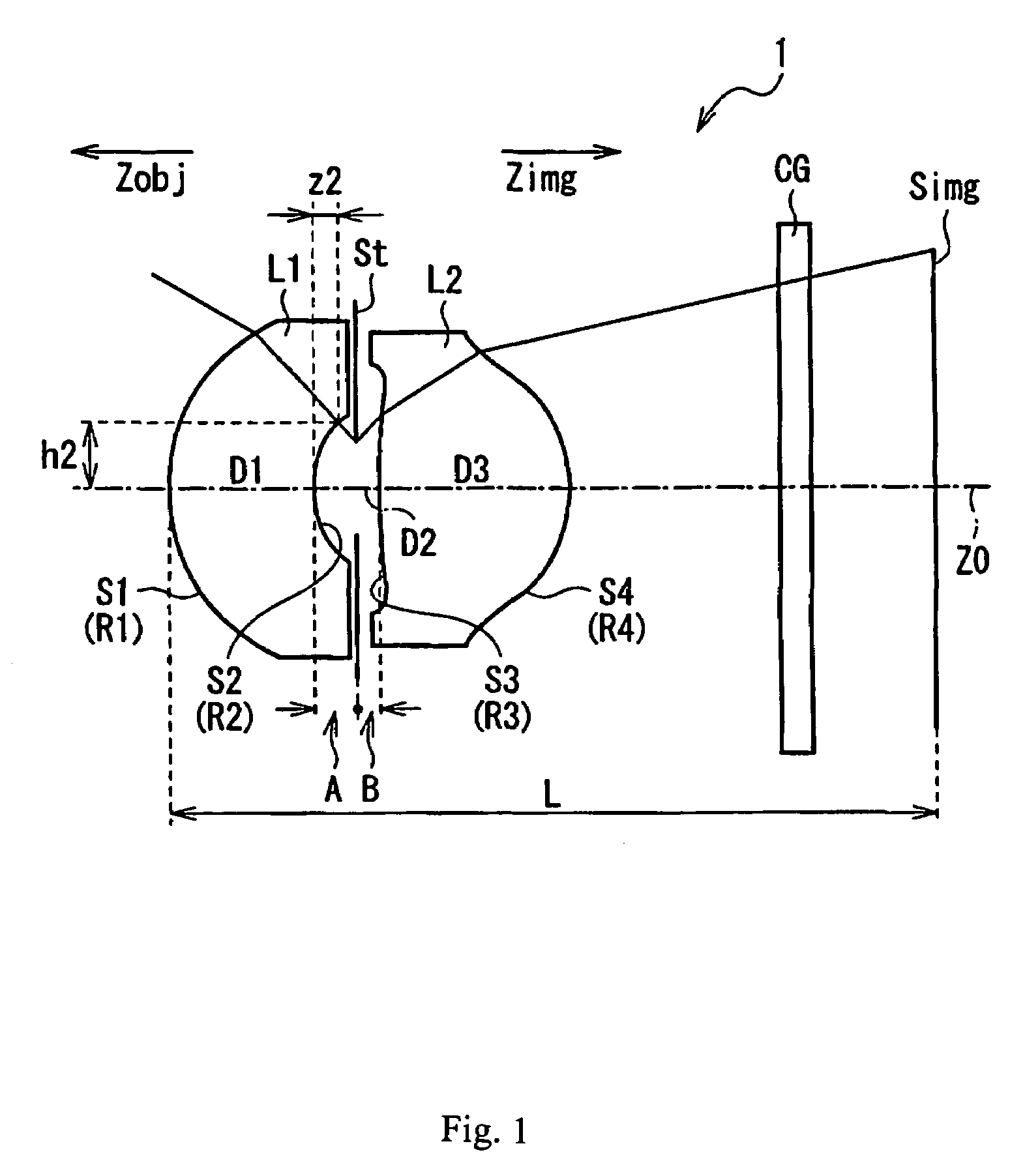
[0083]FIG. 1 shows Embodiment 1 of the present invention. Table 1 below lists the surface number #, in order from the object side, the radius of curvature R (in mm) of each surface near the optical axis, the on-axis surface spacing D (in mm), as well as the refractive index Ne (at the e-line of λ=546.1 nm) and the Abbe number νd (at the d-line of λ=587.6 nm) of each lens element for Embodiment 1. Listed in the bottom portion of Table 1 are the values of f, f1, f2, D, h2, and z2 (all in mm), which have been defined with respect to Conditions (1)–(3) and (6)–(8) above, for Embodiment 1. Also listed in the bottom of Table 1 are the distance L (in mm) along the optical axis Z0 from the first lens surface S1 of the first lens element L1 to the image plane Simg for an in-focus image of an object at infinity for Embodiment 1, the distances A and B (both in mm) defined above in relation to the position of the stop St and the vertices of lens surfaces S2 and S3, and the ratio B / A.

[0084]

TABLE...

embodiment 2

[0090]Embodiment 2 is very similar to Embodiment 1 and is well shown by FIG. 1. Table 3 below lists the surface number #, in order from the object side, the radius of curvature R (in mm) of each surface near the optical axis, the on-axis surface spacing D (in mm), as well as the refractive index Ne (at the e-line of λ=546.1 nm) and the Abbe number νd (at the d-line of λ=587.6 nm) of each lens element for Embodiment 2. Listed in the bottom portion of Table 3 are the values of f, f1, f2, D, h2, and z2 (all in mm), which have been defined with respect to Conditions (1)–(3) and (6)–(8) above, for Embodiment 2. Also listed in the bottom of Table 3 are the distance L (in mm) along the optical axis Z0 from the first lens surface S1 of the first lens element L1 to the image plane Simg for an in-focus image of an object at infinity for Embodiment 2, the distances A and B (both in mm) defined above in relation to the position of the stop St and the vertices of lens surfaces S2 and S3, and the...

embodiment 3

[0097]Embodiment 3 is very similar to Embodiment 1 and is well shown by FIG. 1. Table 5 2below lists the surface number #, in order from the object side, the radius of curvature R (in mm) of each surface near the optical axis, the on-axis surface spacing D (in mm), as well as the refractive index Ne (at the e-line of λ=546.1 nm) and the Abbe number νd (at the d-line of λ=587.6 nm) of each lens element for Embodiment 3. Listed in the bottom portion of Table 5 are the values of f1, f2, D, h2, and z2 (all in mm), which have been defined with respect to Conditions (1)–(3) and (6)–(8) above, for Embodiment 3. Also listed in the bottom of Table 5 are the distance L (in mm) along the optical axis Z0 from the first lens surface S1 of the first lens element L1 to the image plane Simg for an in-focus image of an object at infinity for Embodiment 3, the distances A and B (both in mm) defined above in relation to the position of the stop St and the vertices of lens surfaces S2 and S3, and the r...


PUM


Abstract

An imaging lens for an image pickup device consists of two lens components that may each consist of a lens element. In order from the object side, these lens components have negative and positive refractive power, with each lens component having two aspheric surfaces. A stop is positioned between the lens components so as to be closer to the image-side lens component. Specified conditions are satisfied in order to miniaturize the imaging lens, reduce manufacturing and assembly costs, and improve imaging performance.

Description

BACKGROUND OF THE INVENTION[0001]Recently, digital still cameras (hereinafter referred to simply as digital cameras) and portable terminal devices, such as portable telephones, that include a camera have become very popular. These cameras convert an image obtained through imaging optics to an electrical signal using an image pickup element, such as a CCD (charge-coupled device) or a CMOS (complementary metal-oxide-semiconductor), and record the signal as image data. In such cameras, a small wide-angle imaging lens is required. In particular, many two-component, two-element imaging lenses have been proposed based on their low cost and small size. For example, Japanese Laid-Open Patent Applications H06-067089, H11-295592, and 2001-183578 disclose such imaging lenses.[0002]Japanese Laid-Open Patent Application H06-067089 disclose imaging lenses that include a first lens element made of plastic (i.e., synthetic resin) having negative refractive power and a meniscus shape with its convex...

Claims


Application Information

Patent Timeline
Patent Type & Authority Patents(United States)
IPC IPC(8): G02B15/14G02B9/04G02B13/00G02B13/18
CPCG02B13/003G02B9/04
Inventor YAMAKAWA, HIROMITSU
Owner FUJI PHOTO OPTICAL CO LTD
Why Eureka
Try Eureka