Frequency converter and its control method

Inactive Publication Date: 2006-04-25
VACON OY +1
View PDF2 Cites 19 Cited by
  • Summary
  • Abstract
  • Description
  • Claims
  • Application Information

AI Technical Summary

Benefits of technology

[0012]One object of the present invention is to eliminate the drawbacks of prior-art solutions, especially in applications which allow high fluctuation in the shaft torque, a

Problems solved by technology

This kind of line current waveform causes problems; e.g., in component dimensioning, and it can cause electric noise problems in the supply line.
These requireme

Method used


Image

  • Frequency converter and its control method
  • Frequency converter and its control method
  • Frequency converter and its control method

Examples


Embodiment Construction

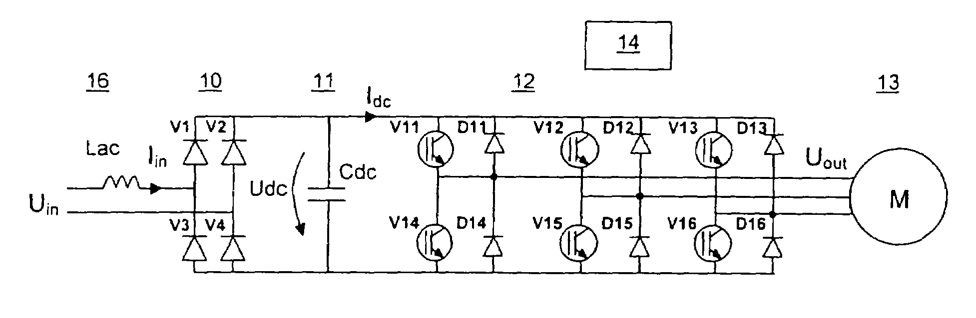
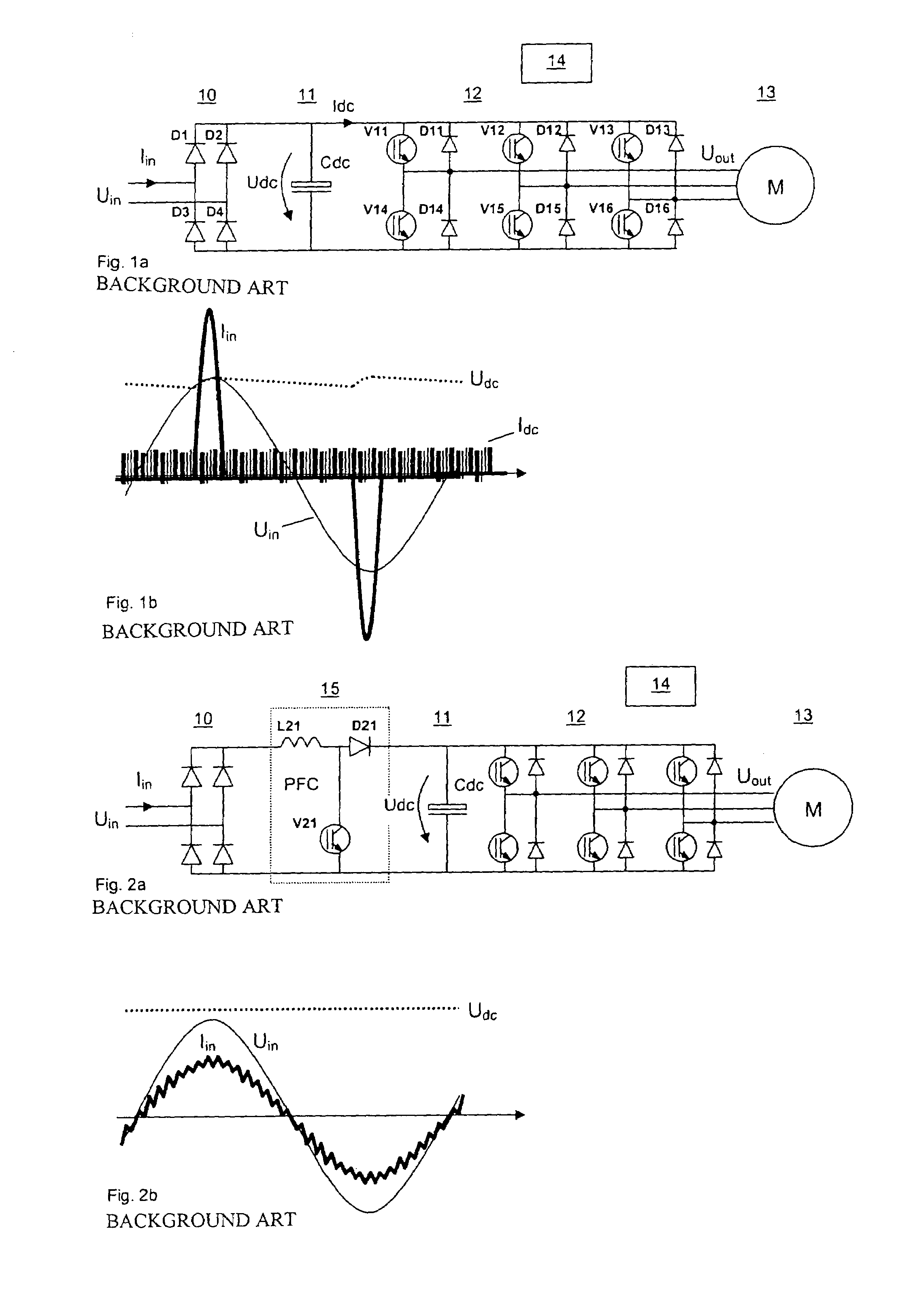
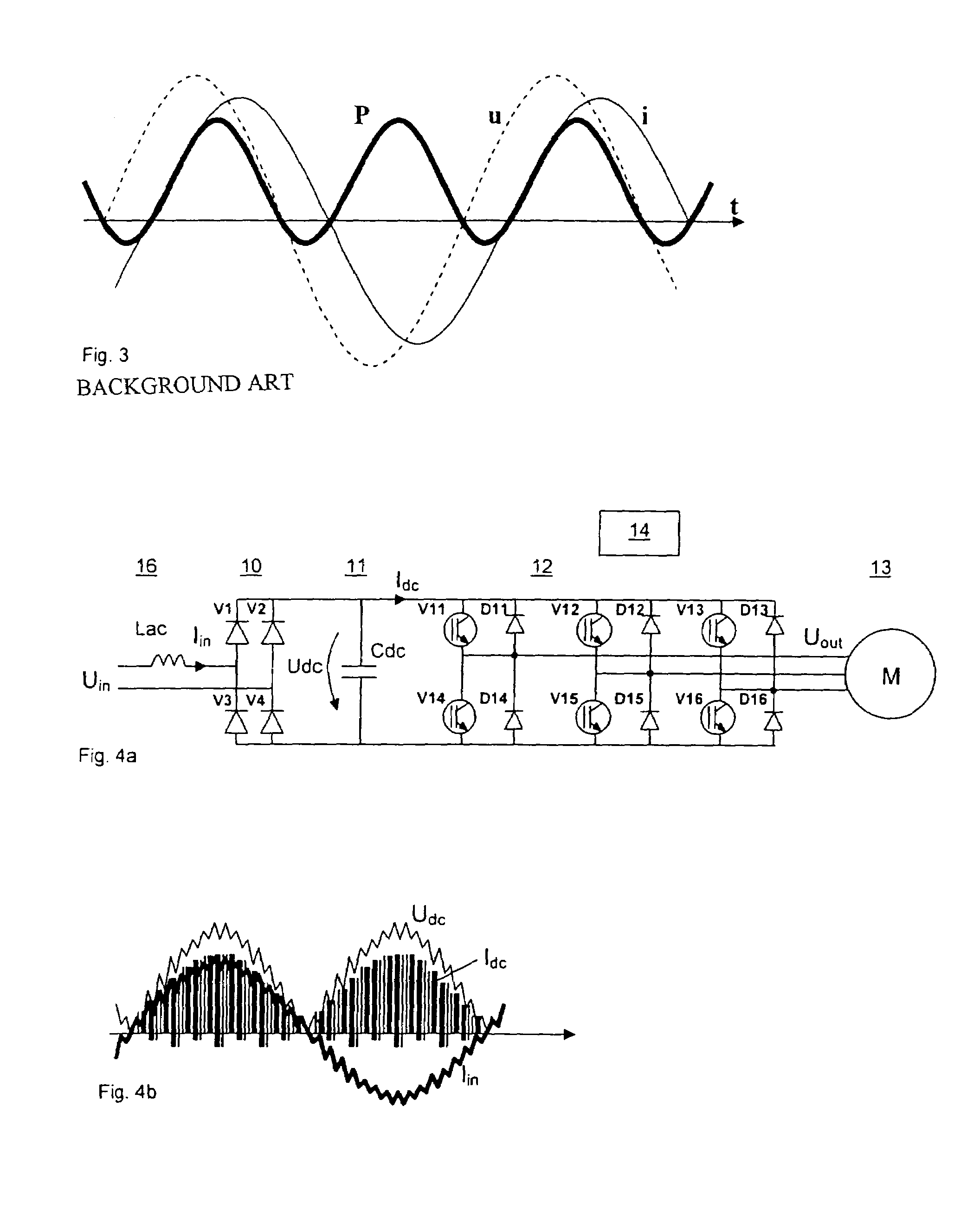
[0025]FIG. 4a presents a single phase PWM frequency converter according to the present invention. As in the prior art (see FIG. 1a), the PWM frequency converter of the present invention includes a rectifier bridge 10 for rectifying an AC voltage Uin of a supply line to a DC voltage Udc for a DC intermediate circuit 11 and a three phase inverter bridge 12 for the inversion of the intermediate circuit DC voltage Udc into a single phase or three phase variable frequency AC voltage Uout. The frequency converter is connected to small three phase AC load, such as a pump or fan motor 13. The inverter bridge 12 is a full-wave bridge with pulse-width-modulated semiconductor switches V11 to V16, such as insulated gate bipolar transistors (IGBTs), and flywheel diodes D11 to D16 connected in inverse-parallel with the semiconductor switches. The semiconductor switches V11 to V16 are controlled with pulse-width modulation by means of a PWM control unit 14. The rectifier bridge 10 may be a full-wa...


PUM


Abstract

Method of controlling a voltage controlled PWM (Pulse Width Modulated) frequency converter comprising a single phase rectifier bridge (10) connectable to a sinusoidal single phase supply, a DC intermediate circuit (11) and a controlled inverter bridge (12) for generating an AC output voltage with varying amplitude and frequency to a load, said inverter bridge (12) having PWM controlled semiconductor switches (V11–V16) and flywheel diodes (D11–D16) connected in inverse-parallel with the semiconductor switches, wherein the DC intermediate circuit (11) is provided with a DC capacitor unit, and wherein the frequency converter is controlled so that the supply line current (Iin) is essentially sinusoidal and in phase with the supply line voltage (Uin). The inverter bridge is controlled so that the curve of filtered average current (Idc) in the DC intermediate circuit follows essentially the curve of the rectified AC supply voltage (Udc), the rectifier bridge is (10) connected to the inverter bridge (12) directly without a DC capacitor unit acting as an intermediate energy storage, and the curve of the power fed to the load has essentially the form sin2(2πft) (f=line frequency t=time).

Description

CROSS-REFERENCE TO RELATED APPLICATION[0001]This Nonprovisional application claims priority under 35 U.S.C. § 119(a) on Patent Application No. 03077175.2 filed in EUROPE on Jul. 7, 2003, the entire contents of which are hereby incorporated by reference.BACKGROUND OF THE INVENTION[0002]1. Field of the Invention[0003]The present invention relates to a voltage controlled PWM (Pulse Width Modulated) frequency converter comprising a single phase rectifier bridge, a DC intermediate circuit and a controlled inverter bridge for generating an AC output voltage with varying voltage and frequency. The present invention also relates to a method for controlling such a frequency converter.[0004]2. Description of Background Art[0005]FIG. 1a presents a prior art single phase PWM frequency converter. It comprises a rectifier bridge 10 for rectifying an AC voltage Uin of a supply line to a DC voltage Udc for a DC intermediate circuit 11 and an inverter bridge 12 for the inversion of the intermediate ...

Claims


Application Information

Patent Timeline
IPC IPC(8): H02M5/45H02M7/06H02M1/00H02M1/42H02M5/458
CPCH02M1/425H02M5/458Y02B70/126Y02B70/10
Inventor SCHREIBER, DEJANPYRHONEN, OLLISILVENTOINEN, PERTTIKOMULAINEN, RISTO
Owner VACON OY
Why Eureka
Try Eureka