Switching power supply and control method for the same

Inactive Publication Date: 2006-04-25
PANASONIC CORP
View PDF3 Cites 21 Cited by
  • Summary
  • Abstract
  • Description
  • Claims
  • Application Information

AI Technical Summary

Benefits of technology

[0042]The present invention is intended to provide a switching power supply being highly stable, compact and highly efficient, capable of attaining the object of carrying out the simultaneous use of the series connection system on the input sides of switching power supply cir

Problems solved by technology

As a result, there is a problem of increasing the outer dimensions of the transformer.
As a result, the loss in the semiconductor device increases, and radiating means for dissipating the heat due to this loss is made larger, whereby it is difficult to make the apparatus more compact.
However, the conventional switching power supply has a problem with respect to the stability of the output voltage.
On the other hand, in the current mode control system, the output is stabl

Method used


Image

  • Switching power supply and control method for the same
  • Switching power supply and control method for the same
  • Switching power supply and control method for the same

Examples


embodiment 1

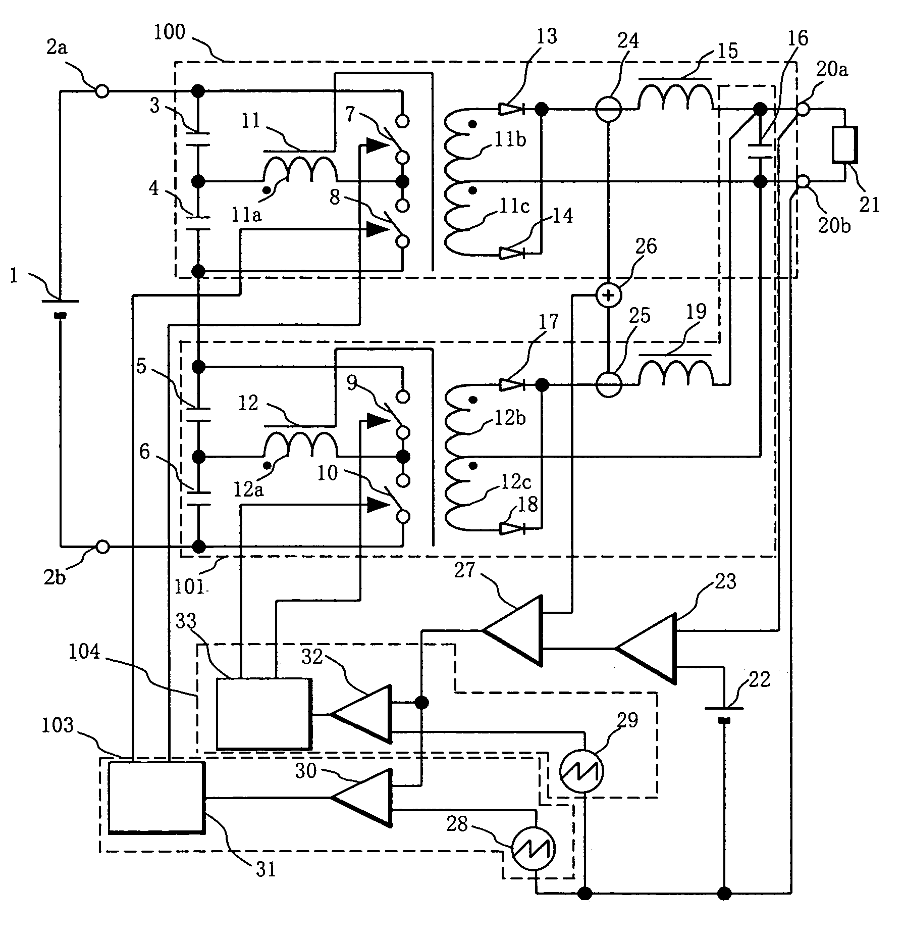
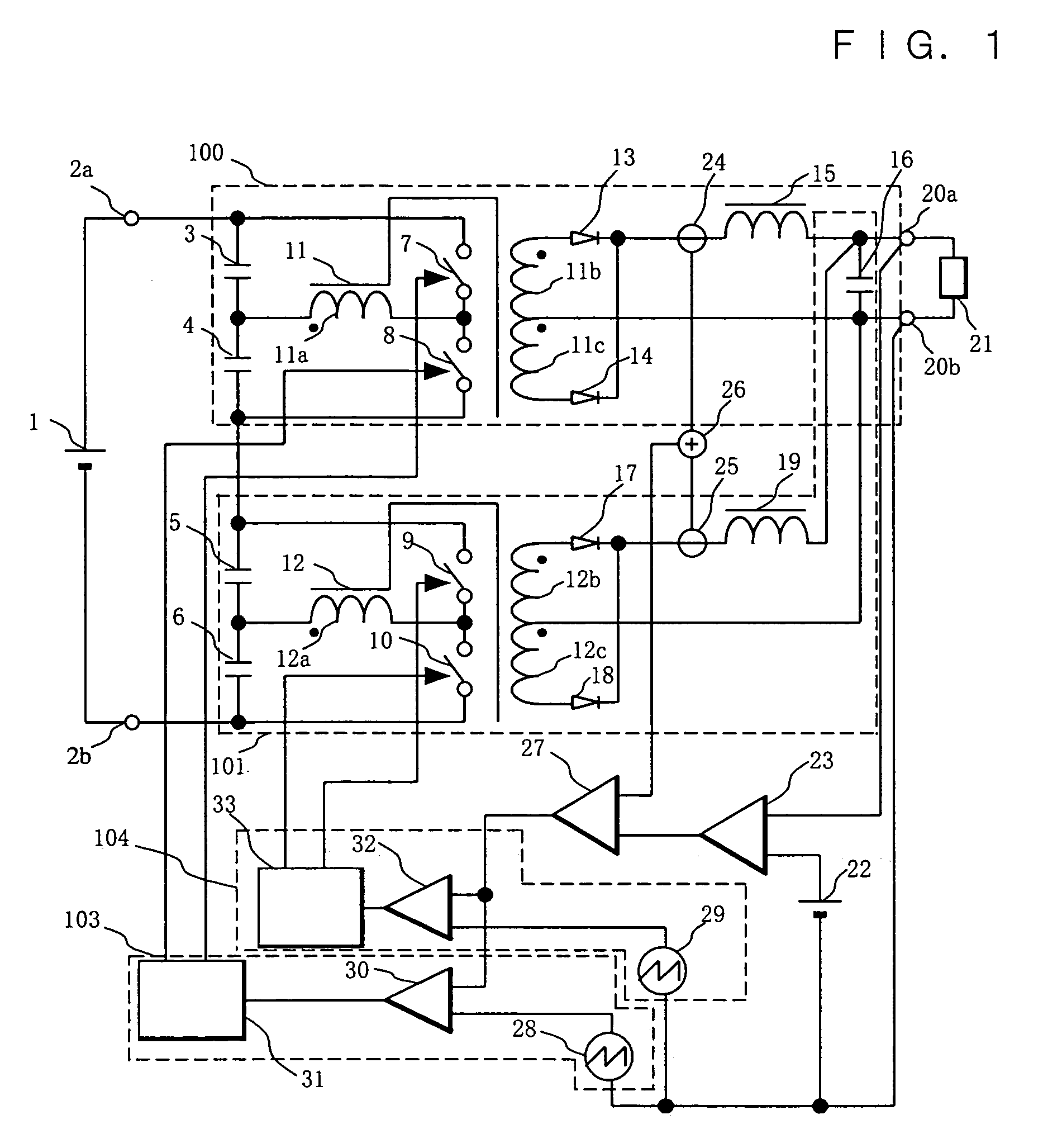
[0063]FIG. 1 is a circuit diagram showing a configuration of a switching power supply in accordance with Embodiment 1 of the present invention. In FIG. 1, the input DC voltage from an input DC power supply 1 is supplied across input terminals 2a and 2b. A series circuit of a plurality of capacitors 3, 4, 5 and 6 is connected across the input terminals 2a and 2b. The input DC voltage applied across the input terminals 2a and 2b is divided by the respective capacitors 3, 4, 5 and 6. In the descriptions given below, the plurality of capacitors 3, 4, 5 and 6 connected across the input terminals 2a and 2b are referred to as a first capacitor 3, a second capacitor 4, a third capacitor 5 and a fourth capacitor 6, respectively. The series circuit of a first switching device 7 and a second switching device 8 is connected across both ends of the series circuit of the first capacitor 3 and the second capacitor 4. Furthermore, the series circuit of a third switching device 9 and a fourth switch...

embodiment 2

[0098]FIG. 3 is a circuit diagram showing a configuration of a switching power supply in accordance with Embodiment 2 of the present invention. The switching power supply in accordance with Embodiment 2 differs from the switching power supply in accordance with Embodiment 1 in the number of half-bridge converters serving as converters. The switching power supply in accordance with Embodiment 1 comprises two half-bridge converters, but the switching power supply in accordance with Embodiment 2 comprises three half-bridge converters. Since the operation of each converter is the same as that described in the explanation of the above-mentioned Embodiment 1, its explanation is omitted herein to prevent overlapping.

[0099]In FIG. 3, the input DC voltage from an input DC power supply 1 is supplied across input terminals 2a and 2b. The respective input sides of a first half-bridge converter 300, a second half-bridge converter 303 and a third half-bridge converter 306 are connected in series ...


PUM


Abstract

In a switching power supply and a control method for the same in accordance with the present invention, a first error amplifier generates a first error signal by comparing the output signals of a plurality of converters with a reference voltage, an arithmetic unit generates a single output signal by adding the currents output from the rectifying means of the plurality of converters, a second error amplifier generates a second error signal by comparing the single output signal with the output of the first error amplifier, and PWM signal generators generate PWM signals on the basis of the output signal of the second error amplifier to PWM control each of a plurality of switching devices.

Description

BACKGROUND OF THE INVENTION[0001]The present invention relates to a switching power supply for supplying a stabilized DC voltage to industrial and consumer electronic appliances and to a control method for the same. More particularly, the present invention relates to improvements in the stability of a switching power supply comprising a plurality of switching power supply circuits.[0002]In recent years, as electronic appliances are made more inexpensive, compact, efficient and energy saving, switching power supplies being inexpensive, compact and efficient and having output stability are demanded strongly as power supplies for use in these electronic appliances. In particular, in the case of power supplies for supplying electric power to semiconductor devices, as semiconductor devices are made more highly integrated, power supplies having higher stability at a lower voltage and capable of supplying a larger current are demanded strongly. In a switching power supply circuit in a swit...

Claims


Application Information

Patent Timeline
IPC IPC(8): H02M7/48H02M3/335H02M3/28
CPCH02M3/285
Inventor YOSHIDA, KOJI
Owner PANASONIC CORP
Why Eureka
Try Eureka