

Method for synchronization adaptation of asynchronous digital data streams
- Summary
- Abstract
- Description
- Claims
- Application Information
AI Technical Summary
Benefits of technology
Problems solved by technology
Method used
Image

Examples
first embodiment
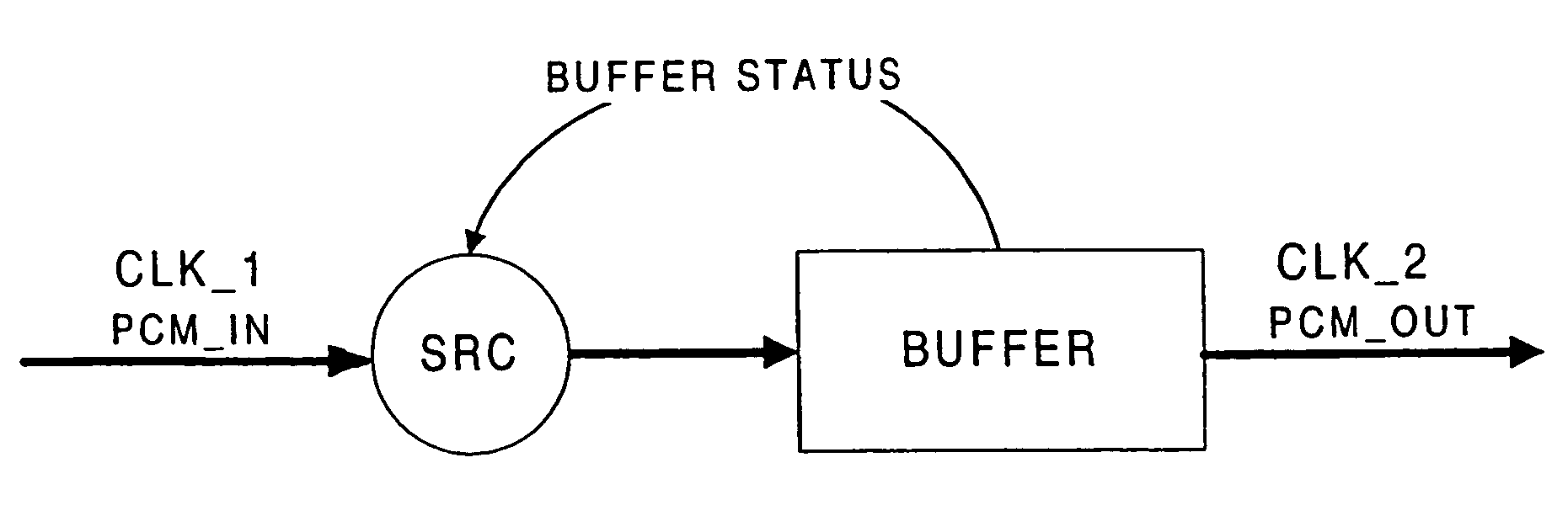
[0034]FIG. 4 illustrates the present invention implementing such a feedback control loop for controlling the sample rate converter SRC.
[0035]As shown in FIG. 4, a first digital data stream PCM_IN consisting of e.g. PCM audio data, being transmitted at a first sample rate CLK_1, is supplied to a sample rate converter SRC, and an output of the sample rate converter is connected to a buffer as a signal processing element to thereby supply data output from said sample rate converter SRC to said buffer for being temporarily stored therein. Further, after being temporarily stored in the buffer, the stored data are output as a second digital data stream PCM_OUT being transmitted at a second sample rate CLK_2, with the second sample rate (clock rate) CLK_2 being different from the first sample rate CLK_1.
[0036]Insofar, the arrangement shown in FIG. 4 is similar to the one described herein above in connection with FIG. 3B. The main difference between the prior art arrangement depicted in FIG...
second embodiment
[0066]In particular, the feedback control loop for control of the sample rate converter SRC based on the detected buffer status has been modified. That is, a means RD adapted to cause random delay has been inserted in the feedback loop in order to ensure that the filtering does not occur repeatedly at a constant rate, to thereby reduce the audibility of the filtering. Such a randomizing changes the nature of the noise to a less annoying wideband impulse noise.
[0067]With regard to the specific example described above, it has to be noted that randomizing of the resampling time has to be used if the resampling is done for many subsequent groups of 160 PCM samples. Without randomizing, a 50 Hz wideband noise would occur in the sound obtained from the transmitted PCM audio data. The audibility of the filtering can be reduced by assuring that the filtering does not occur at exactly a constant rate by adding a random delay means RD causing random delay to the process. In particular, in th...
PUM
 Abstract
Description
Claims
Application Information