Process for treating coil end upon winding of coil

a technology of coil end and coil winding, which is applied in the direction of magnets, manufacturing tools, magnets, etc., can solve the problems of deteriorating the reliability of the product and incomplete welding, and achieve the effects of high reliability, sufficient utilization of arc welding, and improved workability

Active Publication Date: 2006-05-02
GOTO DENISH CO LTD
View PDF8 Cites 4 Cited by
  • Summary
  • Abstract
  • Description
  • Claims
  • Application Information

AI Technical Summary

Benefits of technology

[0016]With the process described above, since the insulating coating is stripped off from the portions of the wire at the front and rear ends of the coil, the merit of the arc welding can be sufficiently utilized. Further, the workability can be improved, the electric connection between the portion of the wire at the front or rear end of the coil and the terminal can be securely carried out, and a coil having high reliability and high quality can be provided.

Problems solved by technology

However, in the conventional process for treating a coil end as described above, an insulating coating of a wire (i.e. electric wire) affects an arc restraining the arc from blowing, resulting in an incomplete welding.
As a result, there has been a possibility that the coils thus manufactured might include a defective coil, which cannot be used for electrical conduction, thereby deteriorating the reliability of the product.

Method used


Image

  • Process for treating coil end upon winding of coil
  • Process for treating coil end upon winding of coil
  • Process for treating coil end upon winding of coil

Examples


Embodiment Construction

[0023]In the following, the preferred embodiments of the present invention will be explained with reference to the attached drawings.

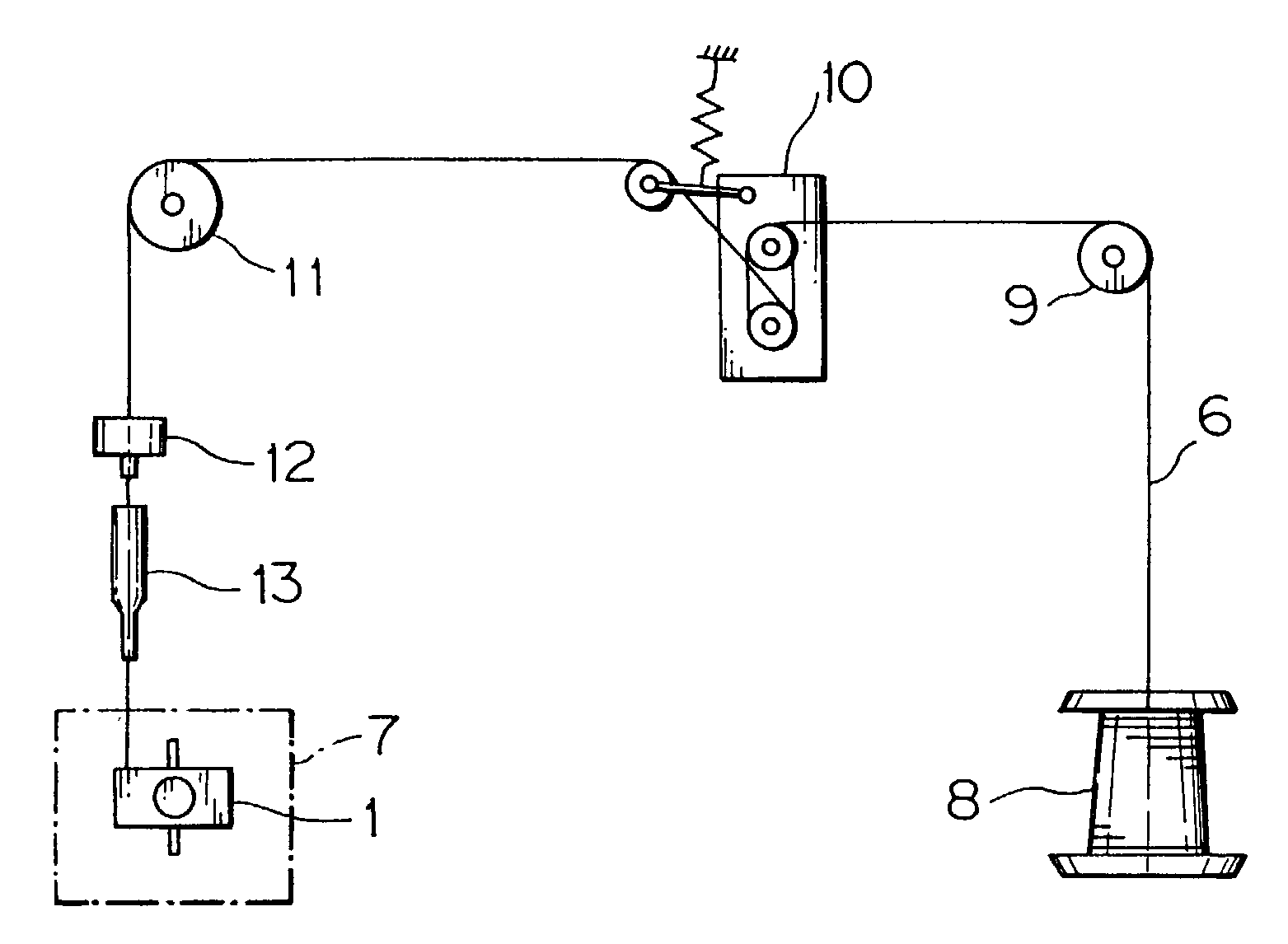
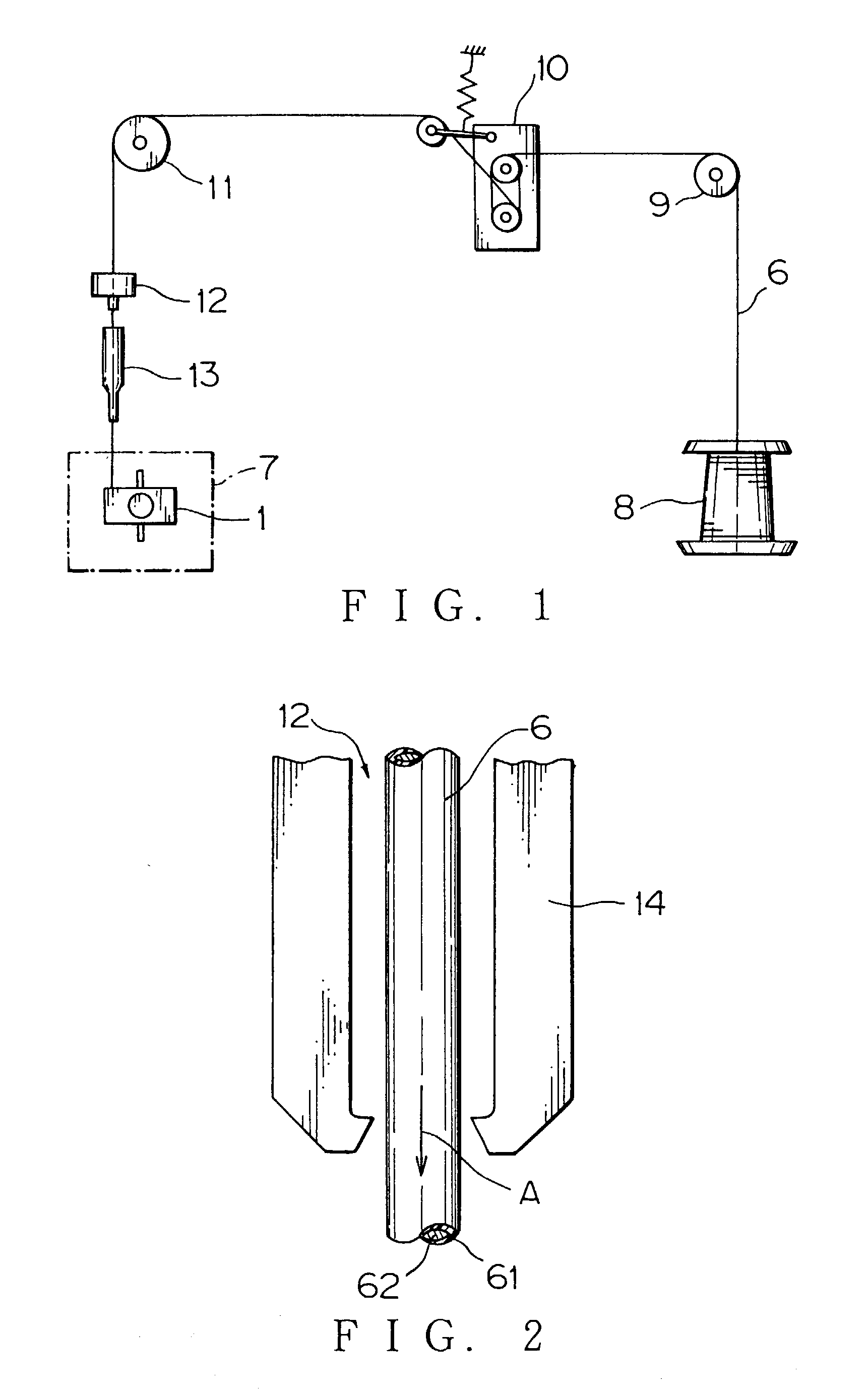
[0024]FIG. 1 is a schematic constitution illustrating a preferred embodiment of a process for treating a coil end upon winding of the coil according to the present invention. A process, in which a wire 6 is conveyed to an automatic coil winding section 7 will be explained with reference to FIG. 1 as follows. First, the wire 6 wound around a wire bobbin 8 is conveyed to a tension mechanism 10 by way of a guide roller 9.

[0025]The wire 6 is provided with a specific tension by the tension mechanism 10 and thereafter is conveyed to a stripping section 12, in which the portions of the wire at the front and rear ends of the coil are subjected to a stripping treatment and thereafter, is conveyed to the automatic coil winding section 7 equipped with a winding subject such as the winding subject 1 shown in FIG. 6 by way of a wire-guiding section 13.

[0026]The str...


PUM

PropertyMeasurementUnit
voltageaaaaaaaaaa
insulatingaaaaaaaaaa
areaaaaaaaaaaa

Abstract

A process for treating a coil end is provided, by which upon automatic winding of the coil, an electric connection between a portion of a wire at the front or rear end of the coil and a terminal of a winding object by arc welding can be securely carried out. A stripping section strips an insulating coating off from the portions of the wire at the front and rear ends of the coil while the wire is wound around the winding object with the portions of the wire being bound to the terminal. Each portion of the wire, the insulating coating of which is stripped off, bound to the terminal is electrically connected to the terminal by arc welding.

Description

BACKGROUND OF THE INVENTION[0001](1) Field of the Invention[0002]The present invention relates to a process for treating a coil end upon automatic winding of the coil used for a motor, relay or transformer, by which each of a portion of the wire (i.e. electric wire) at the front end of the coil and a portion of the wire at the rear end of the coil is bound to a corresponding terminal formed on a winding object.[0003](2) Description of the Related Art[0004]So far, for example, in case of a multi-spindle automatic winding device of coil, each of the portion of the wire at the front end of the coil and the portion of the wire at the rear end of the coil as insulation-treated has been bound to a corresponding metal terminal formed on a winding object such as a coil bobbin by winding each of the wire around the corresponding terminal with about three to six turns.[0005]An example of the winding object is shown in FIG. 6. The winding object 1 is provided with a terminal 2, to which a port...

Claims


Application Information

Patent Timeline
Patent Type & Authority Patents(United States)
IPC IPC(8): H01R43/02H01F5/04H01F41/06H01F41/10H01R43/033
CPCH01F41/0666H01F5/04H01F41/10H01R43/033Y10T29/53213Y10T29/49071Y10T29/49162Y10T29/49073Y10T29/5183Y10T29/514Y10T29/49179Y10T29/49192H01F41/076
Inventor GOTO, YOSHIHIDE
Owner GOTO DENISH CO LTD
Why Eureka
Try Eureka