Latchless controller tower

a controller and lock technology, applied in the direction of mechanical control devices, process and machine control, instruments, etc., can solve the problems of occupying precious portions of limited available space, extra hardware, and extra labor of conventional movable controller towers, so as to reduce the functionality of the system, increase the available space, and facilitate the access of other components.

Inactive Publication Date: 2006-05-02
DEERE & CO
View PDF11 Cites 27 Cited by
  • Summary
  • Abstract
  • Description
  • Claims
  • Application Information

AI Technical Summary

Benefits of technology

[0004]The inventors recognize that conventional movable controller towers require a significant amount of extra hardware for cable and latch mechanisms as well as extra labor to produce and assemble the hardware. Further, the additional hardware occupies precious portions of limited available space that could be used for other valuable purposes. Finally, the transverse shaft, commonly shared by both controller towers in some conventional systems, is exposed to the detriments of the environment as it is located under the cab floor; it also reduces functionality in the system by requiring simultaneous movement of the towers.
[0005]The invention overcomes each of the above mentioned limitations of conventional controller towers via an elegantly simple mechanism. Simple mounting brackets are fixedly attached to portions of the frame or floor on either side of the seat. A shaft, some ball bearings and a snap ring secure each tower to the mounting brackets via a hole in the brackets and serve as a pivot for the independent movement of each tower to each of its positions. A gas filled strut, operatively attached to each tower and corresponding mounting bracket, provides a toggle or over-center effect as each tower is moved from one of its two positions to the other. Thus, an operator may change the position of a tower by pushing or pulling a portion of the tower structure. Adequate extending forces of each strut keeps each of the towers in either of their dual positions, thus eliminating the need for cables and latches to lock the towers. The common rotational shaft, present in some conventional systems, is also eliminated, increasing available space on the underside of the floor for greater access to other components. Finally, the time and cost for parts and labor for each controller tower are reduced.

Problems solved by technology

The inventors recognize that conventional movable controller towers require a significant amount of extra hardware for cable and latch mechanisms as well as extra labor to produce and assemble the hardware.
Further, the additional hardware occupies precious portions of limited available space that could be used for other valuable purposes.
Finally, the transverse shaft, commonly shared by both controller towers in some conventional systems, is exposed to the detriments of the environment as it is located under the cab floor; it also reduces functionality in the system by requiring simultaneous movement of the towers.

Method used


Image

  • Latchless controller tower
  • Latchless controller tower
  • Latchless controller tower

Examples


Embodiment Construction

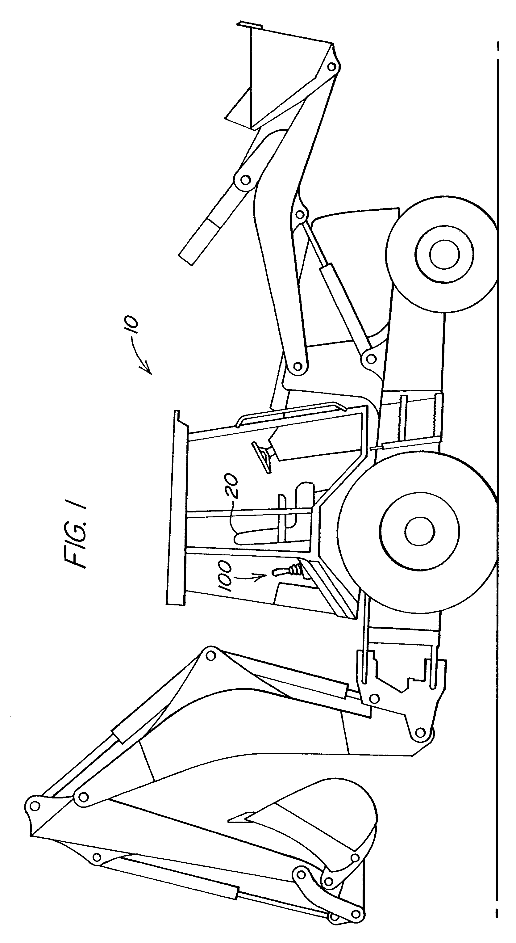
[0012]FIG. 1 illustrates a work vehicle 10 in which the invention may be used. The particular work vehicle illustrated in FIG. 1 is a loader backhoe with a single multiple position swivel seat 20. The multiple positions of the swivel seat 20 include at least a loader operating position and a backhoe operating position and are usually angularly spaced 180° apart. In FIG. 1, the swivel seat 20 is shown in the loader operating position. The work vehicle also has two backhoe control assemblies 100.

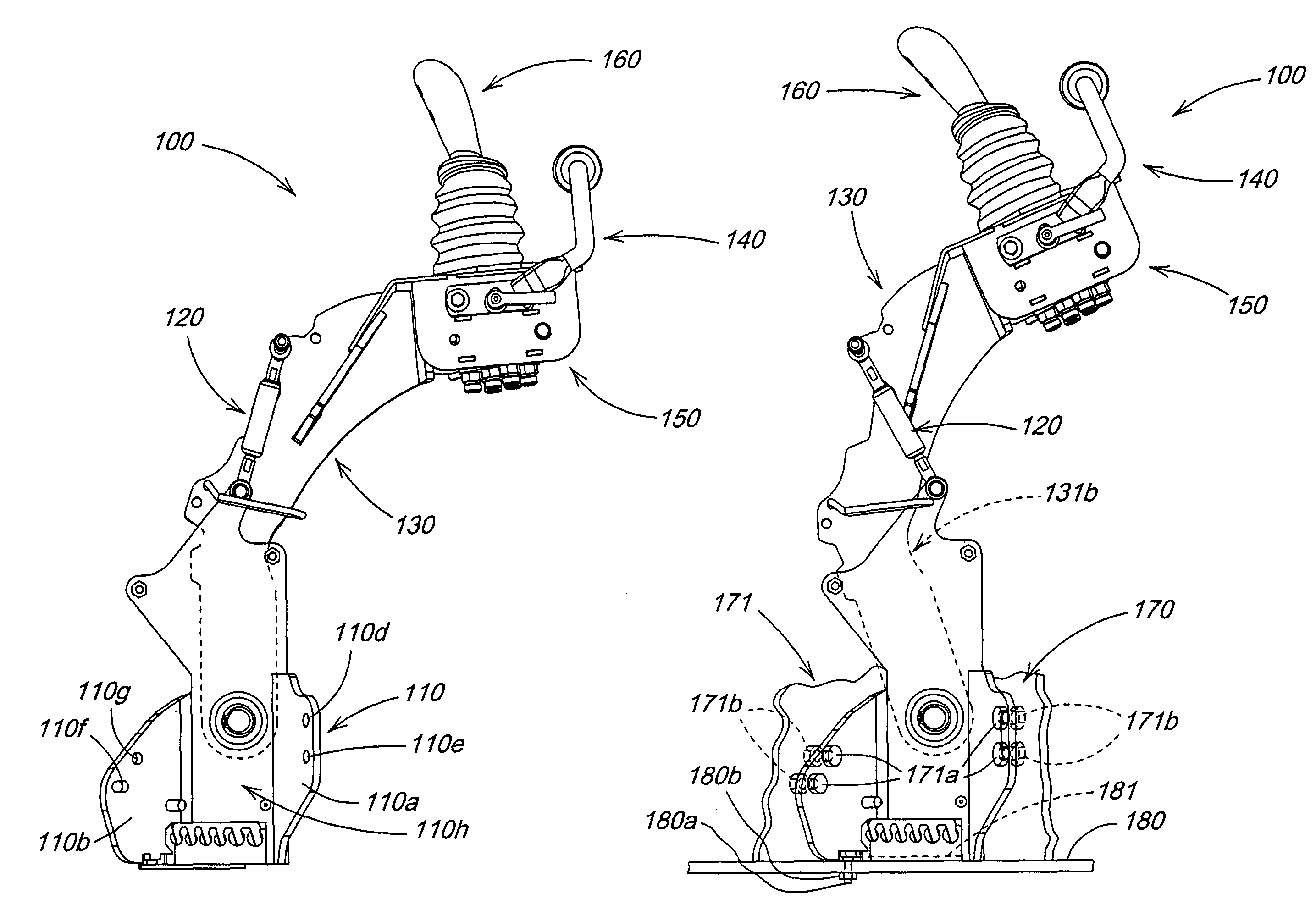
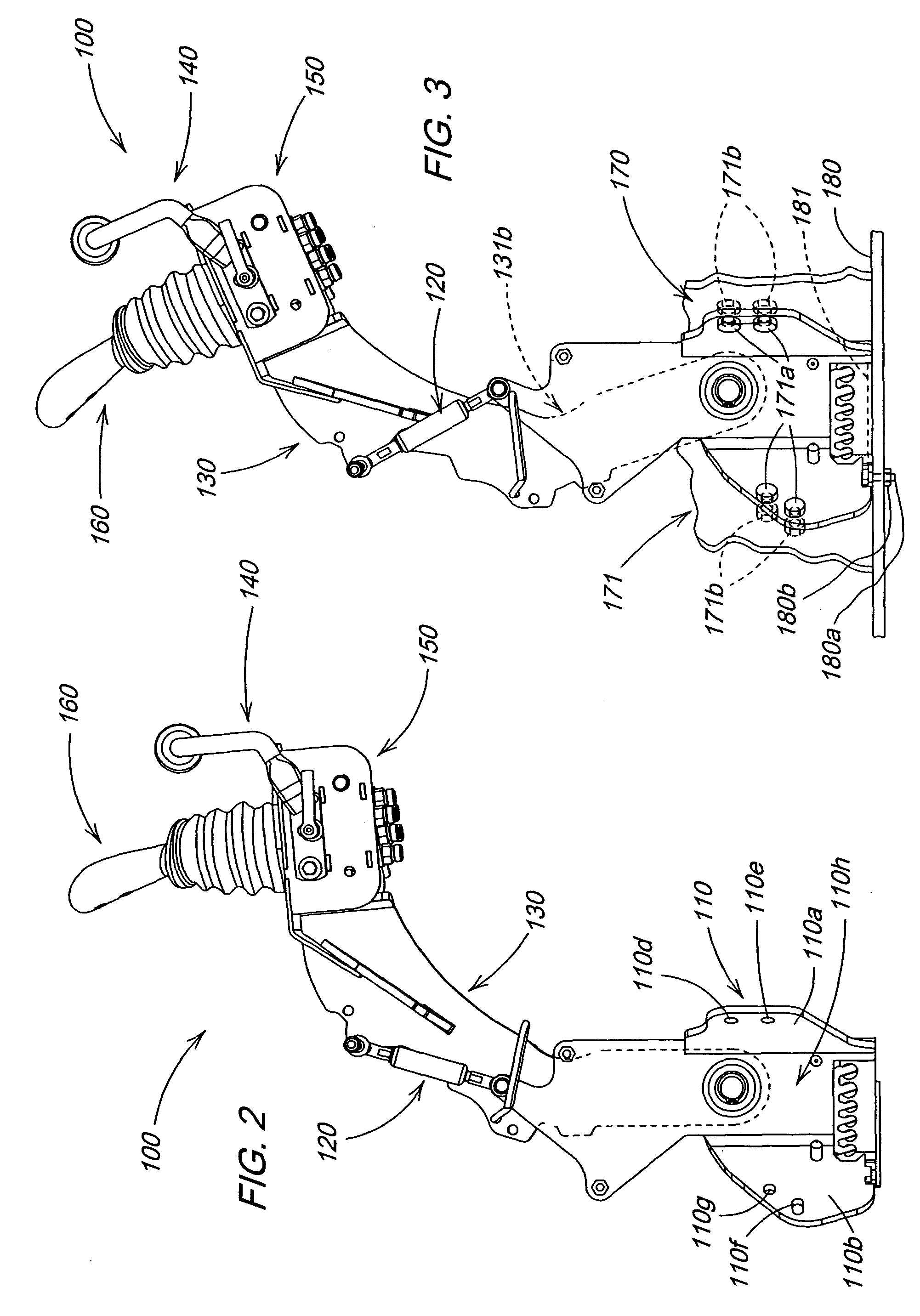
[0013]FIG. 2 illustrates an exemplary embodiment of a backhoe control assembly 100 in the backhoe operating position according to the invention. FIG. 3 shows the same backhoe control assembly 100 in the stow position. The particular control assembly 100 illustrated is located on the left side of the seat when the seat is in the backhoe operating position. Only this control assembly 100 will be described as its working parts are identical to those of the other control assembly (not shown) on th...


PUM


Abstract

A controller tower positioning system for a work vehicle for securing the controller tower to one of at least two positions. The system employs a mounting bracket fixed to the floor or a frame member of the work vehicle, a movable controller tower rotatably mounted to the mounting bracket and a resistive element strategically mounted to the controller tower and the mounting bracket to provide resistance to movement away from either of the two positions and a toggle effect as the controller tower is moved from one of the two positions to the other. The controller assembly is physically restrained at the free end of the controller tower.

Description

FIELD OF THE INVENTION[0001]The invention relates to the positioning and operation of controller towers for backhoes. More specifically, it relates to a method, system and apparatus for safely and securely positioning controller towers to allow the operator to easily and conveniently move the traditional swivel seat often associated with backhoe cabs into and out of the backhoe operating position.BACKGROUND OF THE INVENTION[0002]Backhoes are often equipped with an operator station having a dual position swivel seat which allows the operator to remain seated as he / she pivots between loader and backhoe operations. Such a provision normally requires movable controller towers as controller towers that are properly located for optimum operator convenience and comfort in backhoe operation usually interfere with the operator's legs and / or with the seat as the operator pivots between backhoe and loader functions. The movable controller towers usually have two basic positions: (1) the stow p...

Claims


Application Information

Patent Timeline
Patent Type & Authority Patents(United States)
IPC IPC(8): E02F3/00E02F9/20
CPCE02F9/2004B66C13/56G05G25/00
Inventor DRESSLER, ROBERT PAULMERTEN, JAMES GERARDHACHMANN, ROBERT JOSEPH
Owner DEERE & CO
Why Eureka
Try Eureka