Three-way bleed type proportional electromagnetic valve
a proportional electromagnetic valve and electromagnetic valve technology, applied in the direction of fluid pressure control, process and machine control, instruments, etc., can solve the problems of unstable flow of atf around the ball valve element, increased energy consumed by the oil pump, unstable etc., to achieve stable output pressure and flow rate characteristics, and prevent easy
- Summary
- Abstract
- Description
- Claims
- Application Information
AI Technical Summary
Benefits of technology
Problems solved by technology
Method used
Image
Examples
embodiment 1
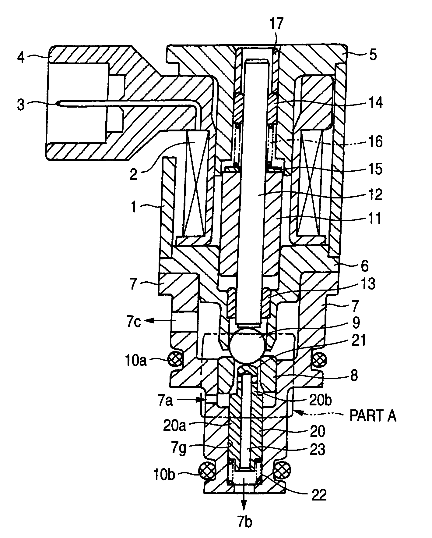
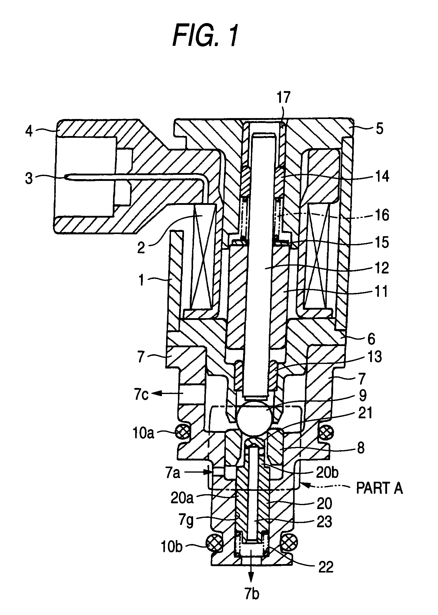
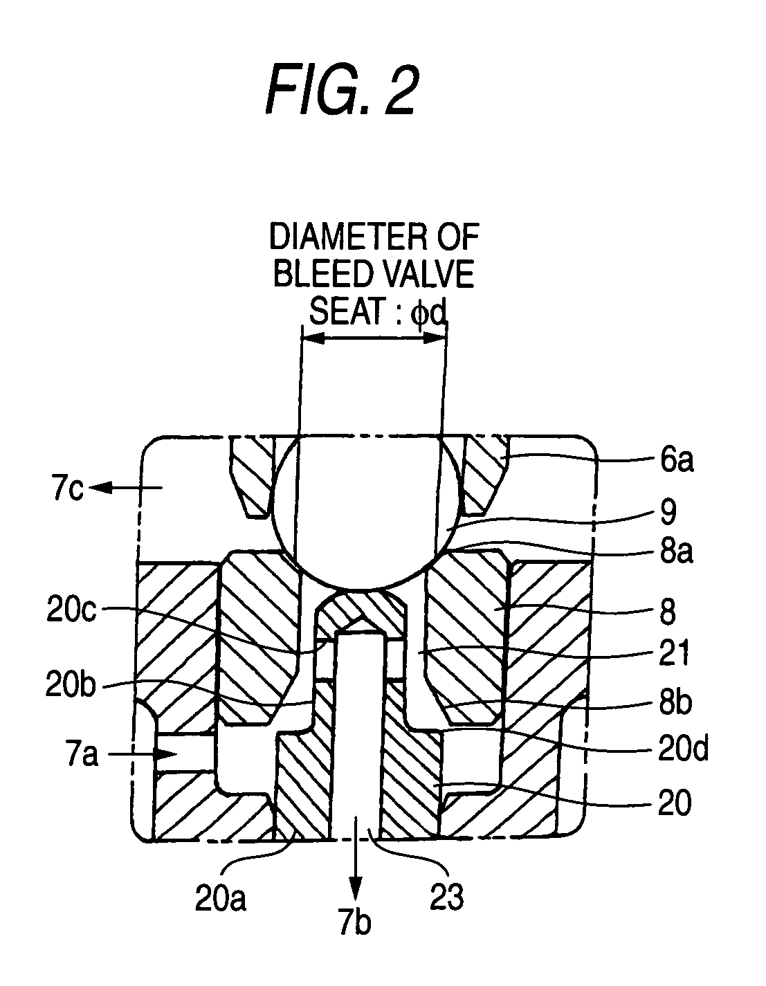
[0040]FIGS. 1–4 are sectional views of an N / H-type, three-way bleed type proportional electromagnetic valve according to a first embodiment of the present invention. FIG. 1 shows states of individual members in a non-energization state, and FIG. 2 is an enlarged view of part A in FIG. 1. Members in FIGS. 1–4 having the same or corresponding members in FIGS. 11 and 12 are given the same reference symbols as the latter and will not be described. The following description will be mainly directed to novel features.
[0041]According to the first embodiment of the invention, a stop valve element 20 is disposed in the flow passage between the input port 7a and the output port 7b of the housing 7. The stop valve element 20 is generally shaped like a cylinder and is stepped, that is, consists of a large-diameter portion 20a and a small-diameter portion 20b. The stop valve element 20 is loosely fit in a stop valve guide 7g (that is formed inside the housing 7 adjacent to the above flow passage)...
embodiment 2
[0049]FIGS. 5 and 6 show an N / L-type, three-way bleed type proportional electromagnetic valve according to a second embodiment of the invention. This valve is similar in configuration to the N / H-type three-way bleed type proportional electromagnetic valve according to the first embodiment and has the same differences from it as the differences between the conventional N / L-type and N / H-type, two-way bleed type proportional electromagnetic valves that were described in the background section. The principle of operation of this N / L-type valve is similar to that of the N / H-type valve according to the first embodiment and hence will be described below only briefly. In a state that the solenoid coil 2 is not energized, as shown in FIG. 5 the stop valve sealing edge 20d of the stop valve element 20 rests on the stop valve seat portion 8b because of the force from the compressed spring 22.
[0050]On the other hand, the bleed valve element 9 is in contact with the stop valve element 20 and is ...
embodiment 3
[0054]FIG. 7 is a sectional view of an N / H-type, three-way bleed type proportional electromagnetic valve according to a third embodiment of the invention which is a modification of the N / H-type, three-way bleed type proportional electromagnetic valve according to the first embodiment. In this embodiment, a guide member 24, which is employed as the stop valve guide 7g of the housing 7, is press-fit in the inner circumferential surface of the housing 7. In the first embodiment, the flow rate of leakage between the input port 7a and the output port 7b, that is, the sealability and the slidability, can be set properly by changing the settings of the radial clearance and the sealing length (i.e., axial length) of the sliding contact portion that consists of the outer circumferential surface of the stop valve element 20 and the stop valve guide 7g of the housing 7. However, the housing 7 should be re-produced each time, which is costly. In contrast, in this embodiment, by virtue of the us...
PUM
 Abstract
Description
Claims
Application Information
 - R&D
- Intellectual Property
- Life Sciences
- Materials
- Tech Scout
- Unparalleled Data Quality
- Higher Quality Content
- 60% Fewer Hallucinations
Browse by: Latest US Patents, China's latest patents, Technical Efficacy Thesaurus, Application Domain, Technology Topic, Popular Technical Reports.
© 2025 PatSnap. All rights reserved.Legal|Privacy policy|Modern Slavery Act Transparency Statement|Sitemap|About US| Contact US: help@patsnap.com


