Stent with self-expanding end sections

Inactive Publication Date: 2006-05-02
SALMON SEAN +4
View PDF15 Cites 117 Cited by
  • Summary
  • Abstract
  • Description
  • Claims
  • Application Information

AI Technical Summary

Benefits of technology

[0006]The goal of the present invention is to overcome several of the potential shortcomings of the existing stents and stent delivery systems. The present invention is a hybrid stent that is defined as having a central section that is balloon expandable and end sections that are self-expanding. The entire stent is mounted by nesting onto a balloon of a balloon

Problems solved by technology

This results in additional time and cost for performing this procedure.
This trauma caused by the balloon expansion beyond the stent edges also occurs with balloon expandable stents.
One disadvantage of existing delivery systems for self-expanding stents (i.e., sheath-like catheters) is that they have a larger diameter as compared to a stent delivery system that does not use a sheath.
Another d

Method used


Image

  • Stent with self-expanding end sections
  • Stent with self-expanding end sections
  • Stent with self-expanding end sections

Examples


Example

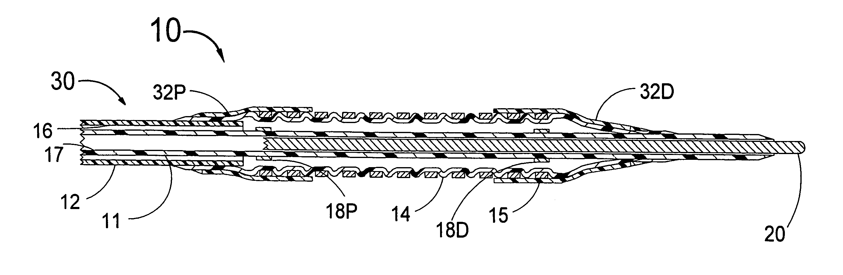
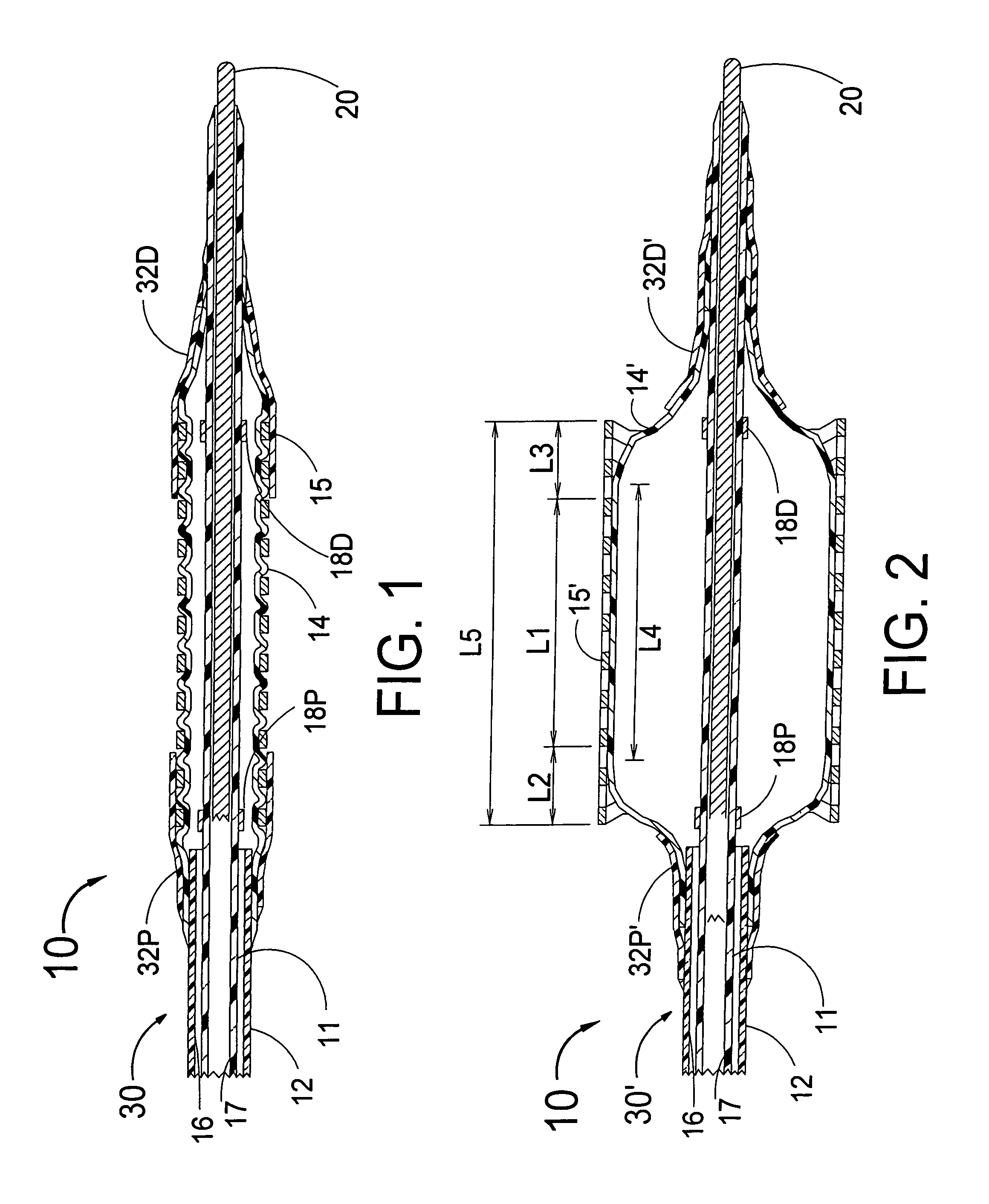
[0027]FIG. 1 is a longitudinal cross section of a distal section of a system 10 that includes a hybrid stent 15, a guide wire 20, a balloon angioplasty catheter 30 and proximal and distal elastomer tubes 32P and 32D. The balloon angioplasty catheter 30 has an inner shaft 11, an outer shaft 12, an inflatable balloon 14, a balloon inflation lumen 16, a guide wire lumen 17, a proximal radio-opaque marker band 18P and a distal radio-opaque marker band 18D. As can be seen in FIG. 1, the balloon 14 has been formed into the interstices of the stent 15, which is a technique called “nesting”. A method for nesting a stent onto a balloon of a balloon angioplasty catheter is described in detail in U.S. patent application Ser. No. 09 / 444,105, incorporated herein by reference.

[0028]The stent 15 would typically be fabricated from the metal “Nitinol” which is a shape-memory alloy that is well known in the art of vascular stents. The transition temperature of the metal of the end sections of the ste...


PUM


Abstract

A hybrid stent that is defined as having a central section that is balloon expandable and end sections that are self-expanding. The entire stent is mounted on a balloon of a balloon angioplasty catheter. One way to retain the self-expanding portion of the stent onto a balloon onto which it has been nested is to place a cylindrical elastomer tube around each of the self-expanding end sections of the stent. Another way to retain the hybrid stent onto a stent delivery system is to use a conventional sheath that is pulled back to initiate stent deployment

Description

[0001]This application is a continuation application of U.S. Ser. No. 09 / 540,629, filed Mar. 31, 2000, now U.S. Pat. No. 6,315,708.FIELD OF USE[0002]This invention is in the field of medical devices to maintain the patency of vessels of the human body.BACKGROUND OF THE INVENTION[0003]Self-expanding stents, particularly those made from the shape-memory alloy Nitinol, are well known in the art of intravascular stents. These stents are typically placed within a sheath-like stent delivery system for placement into a stenosis of a vessel such as an artery of a human body. When the sheath of the stent delivery system is pulled back, the self-expanding stent will deploy radially outward against the wall of a vessel of a human body such as a coronary artery. After they are deployed, it is typically necessary to remove the sheath-like catheter that delivered the stent and then insert a balloon angioplasty catheter for the purpose of further expanding the stent at the site of an arterial sten...

Claims


Application Information

Patent Timeline
IPC IPC(8): A61F2/06A61F2/00A61F2/90
CPCA61F2/90A61F2/958A61F2250/0048A61F2250/0018A61F2250/0042A61F2002/9583
Inventor SALMON, SEANSTOCKEL, DIETERFISCHELL, ROBERT E.FISCHELL, TIM A.FISCHELL, DAVID R.
Owner SALMON SEAN
Why Eureka
Try Eureka