Device for gasifying combustible materials, residues and waste materials containing carbon

a technology of combustible materials and waste materials, which is applied in the direction of combustible gas purification/modification, combustible gas production, lighting and heating apparatus, etc., can solve the problems of limited operating times to be achieved before an expensive refit, long operating times, and the use of ash-free fuel materials. achieve the effect of reliable operation

Inactive Publication Date: 2006-05-02
SIEMENS AG +1
View PDF9 Cites 28 Cited by
  • Summary
  • Abstract
  • Description
  • Claims
  • Application Information

AI Technical Summary

Benefits of technology

[0015]Working on the basis of this prior art, the object of the invention is to provide an appliance which, while being

Problems solved by technology

However, they can only be used for ash-free fuel materials, since the liquid slag which flows off the inner surface of the reaction chamber during the entrained-flow gasification dissolves the refractory lining and therefore only allows very limited operating times to be achieved before an expensive refit is required.
Such systems are extremely robust and guarantee long operating times. A significant drawback of such systems consists in the fact that up to approx.
Various fuel and waste materials, such as for example heavy-metal- or light-ash-containing oils, tar

Method used


Image

  • Device for gasifying combustible materials, residues and waste materials containing carbon
  • Device for gasifying combustible materials, residues and waste materials containing carbon
  • Device for gasifying combustible materials, residues and waste materials containing carbon

Examples


Embodiment Construction

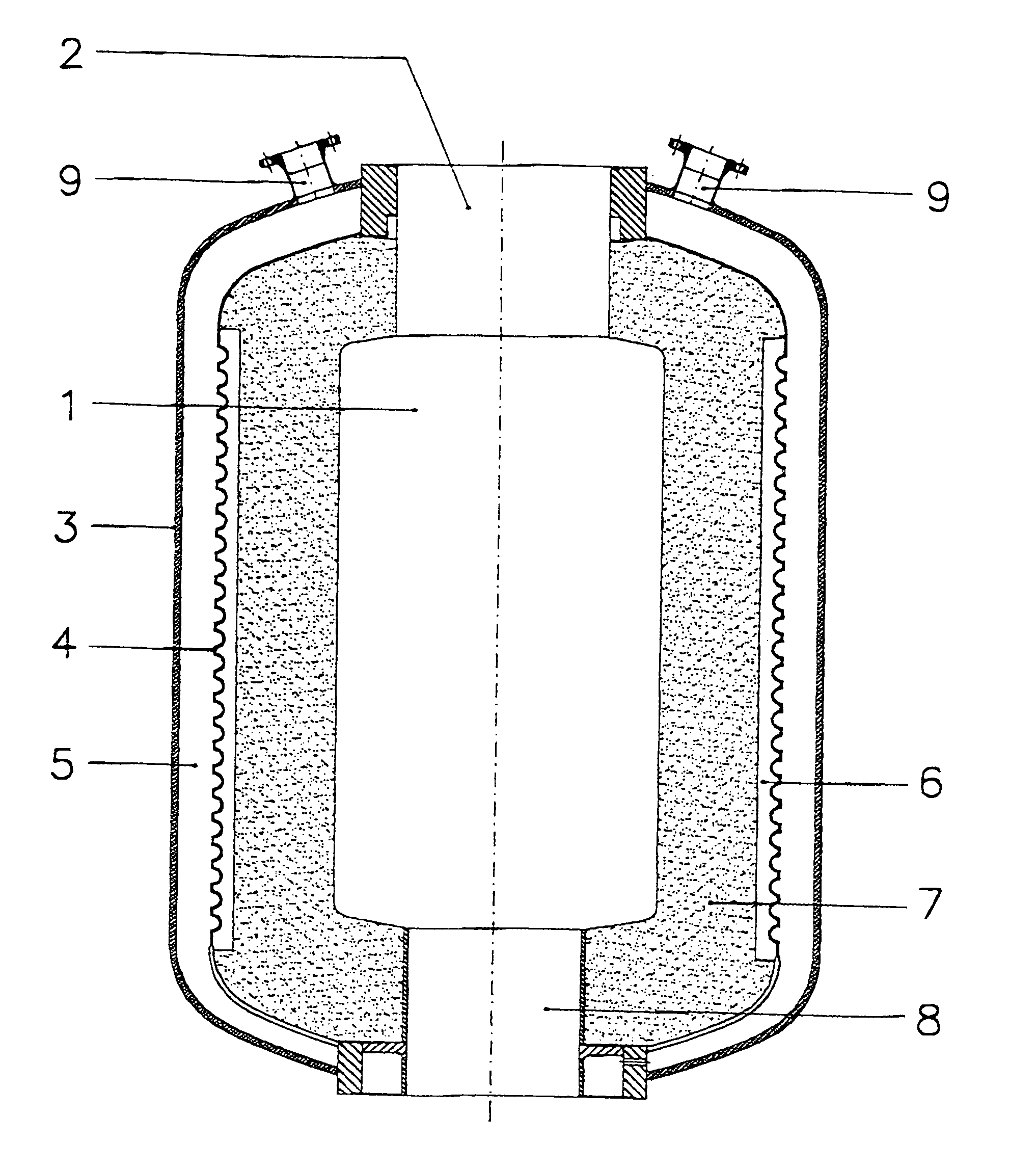
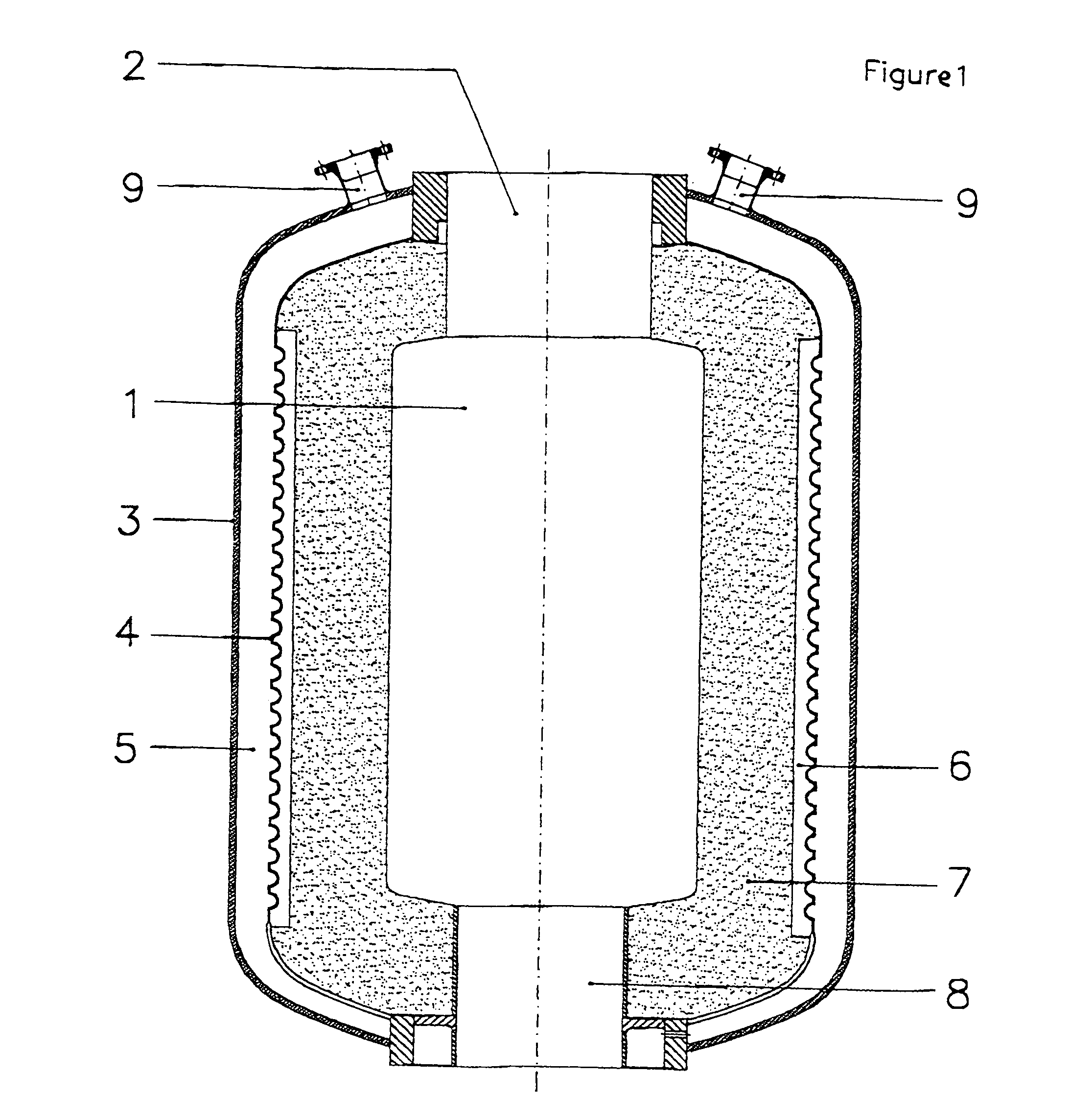
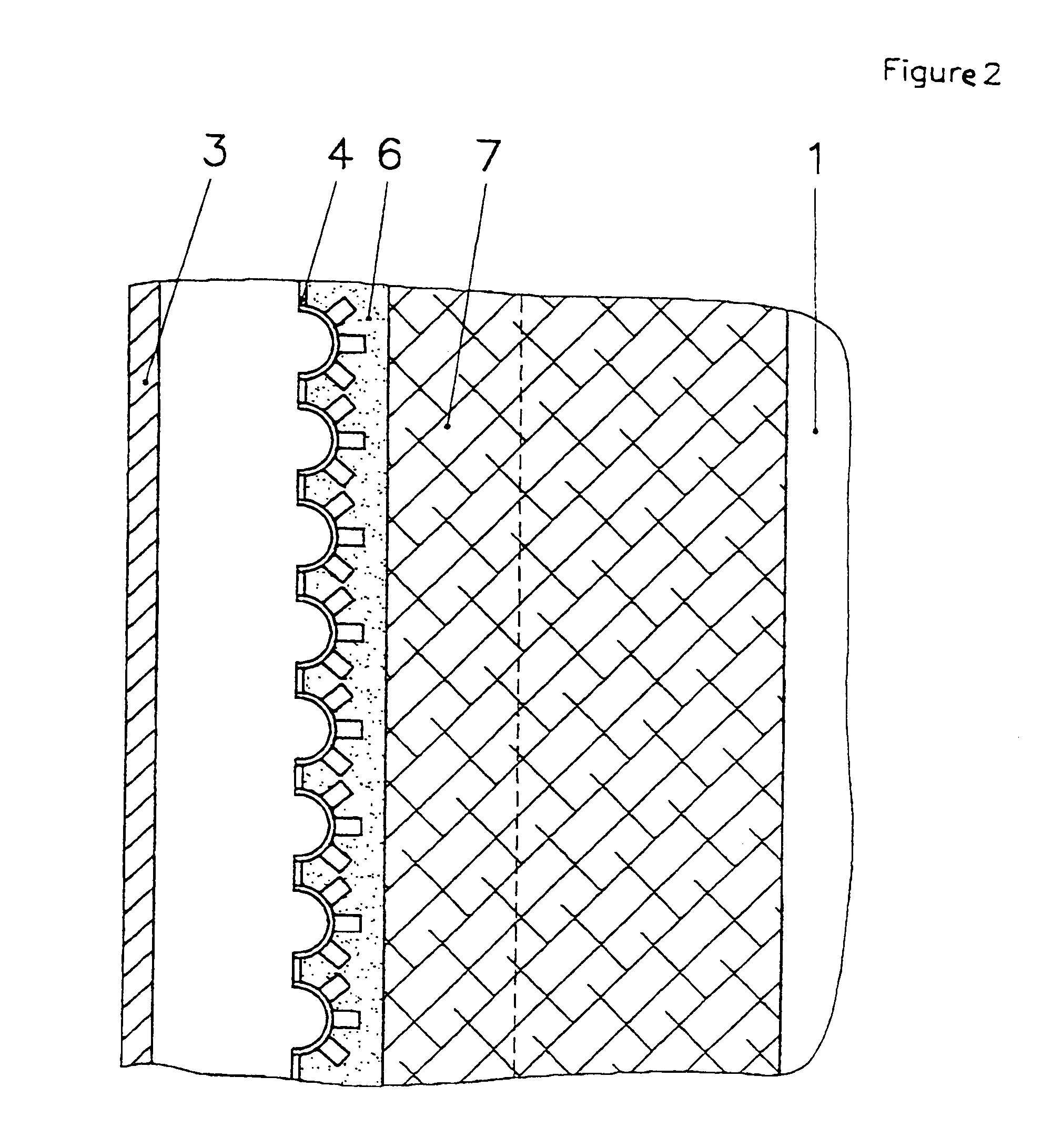
[0022]In the first exemplary embodiment, FIG. 1 shows the gasification reactor. The conversion of the fuel, residual and waste materials using the oxygen-containing oxidizing agent to form a crude gas containing high levels of H2 and CO takes place in the reaction chamber 1. The gasification media are supplied by means of special burners which are attached to the burner flange 2. The crude gasification gas, if appropriate together with liquid slag, leaves the reaction chamber 1 via the opening 8, which is provided with a special appliance, and passes to downstream cooling, scrubbing and processing systems. The gasification reactor is surrounded by the pressure shell 3, which absorbs the difference in pressure between the reaction chamber 1 and the outside atmosphere. For its thermal protection, there is a cooling gap 5 which, filled with water, can be operated above or below the boiling point, which depends on the overall pressure. To prevent gasification gas from entering the cooli...


PUM


Abstract

An appliance for the gasification of carbon- and ash-containing fuel, residual and waste materials using an oxygen-containing oxidizing agent at temperatures above the melting point of the inorganic fractions, in a reaction chamber which is designed as an entrained-bed reactor, at pressures between atmospheric pressure and 80 bar, preferably between atmospheric pressure and 30 bar, the contour of the reaction chamber being delimited by a cooled reactor wall. The cooled reactor wall having the following structure, from the outside inward: a pressure shell, a cooling wall, a water-cooled gap between the pressure shell and the cooling wall, a ceramic protection for the cooling wall, and a layer of slag. The pressure and temperature of the cooling gap between the pressure shell and the cooling wall is controlled in such a way that it can be operated above and below the boiling point of the cooling water. The pressure in the cooling gap is higher than the pressure in the gasification chamber.

Description

PRIORITY CLAIM[0001]This is a U.S. national stage of application No. PCT / DE98 / 01995, filed on Jul. 16, 1998. Priority is claimed on that application and on the following application:[0002]Country: Germany, Application No.: 198 29 385.2, filed: Jul. 1, 1998.BACKGROUND OF THE INVENTION[0003]1. Field of the Invention[0004]The invention relates to an appliance for gasification of carbon-containing fuel, residual and waste materials.[0005]2. Discussion of the Prior Art[0006]Fuel and waste materials are to be understood as meaning those with or without an ash content, such as brown or hard coals and their cokes, water / coal suspensions, but also oils, tars and slurries, as well as residues or wastes from chemical and wood pulping processes, such as for example black liquor from the Kraft process, as well as solid and liquid fractions from the waste management and recycling industry, such as used oils, PCB-containing oils, plastic and domestic refuse fractions or their processing products, ...

Claims


Application Information

Patent Timeline
IPC IPC(8): B01J3/00C10J3/48F28F9/00
CPCC10J3/485F28F9/00C10J3/74C10K1/08C10J3/78F28F2270/00C10J2300/1223
Inventor DONNER, RALFDEGENKOLB, DIETMARSCHINGNITZ, MANFRED
Owner SIEMENS AG
Why Eureka
Try Eureka