Electrophoretic display, method for making the electrophoretic display, and electronic apparatus

Inactive Publication Date: 2006-05-02
SEIKO EPSON CORP
View PDF8 Cites 56 Cited by
  • Summary
  • Abstract
  • Description
  • Claims
  • Application Information

AI Technical Summary

Benefits of technology

[0034]Since such an electronic apparatus uses the above electrophoretic display, th

Problems solved by technology

The liquid crystal displays, however, still have unresolved problems, such as unsatisfactory visibility due to a viewing angle to the screen and reflected light and visual load due to a flickering light source.
Traditional electrophoretic displays using microcapsules, however, have problems such as poor coloring and low contrast because the binder is present between the

Method used


Image

  • Electrophoretic display, method for making the electrophoretic display, and electronic apparatus
  • Electrophoretic display, method for making the electrophoretic display, and electronic apparatus
  • Electrophoretic display, method for making the electrophoretic display, and electronic apparatus

Examples


Example

EXAMPLE 1

[0117]The electrophoretic display shown in FIGS. 1 and 13 was produced as follows:

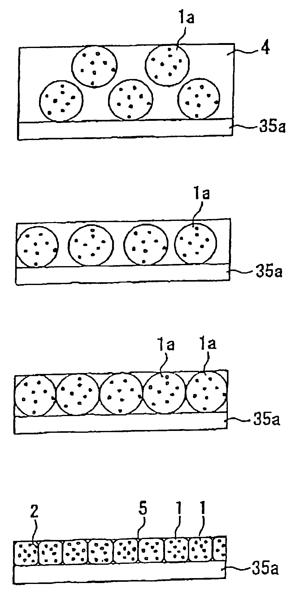
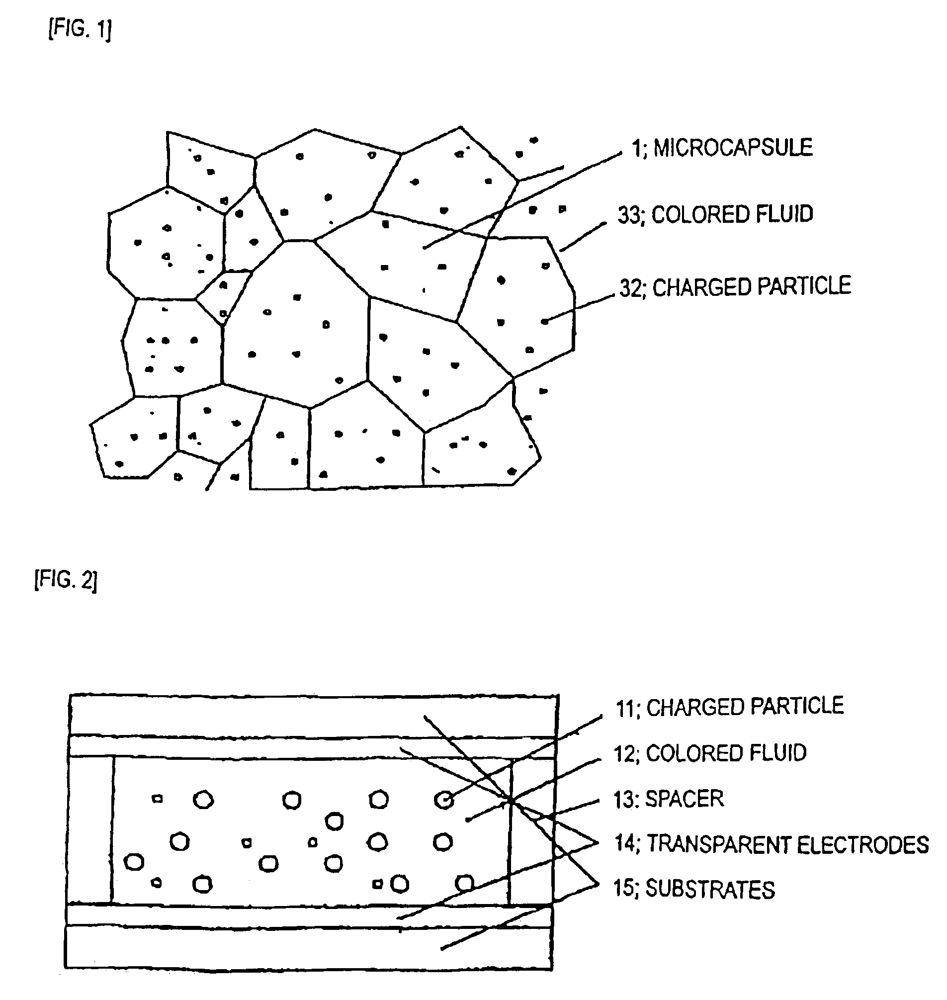
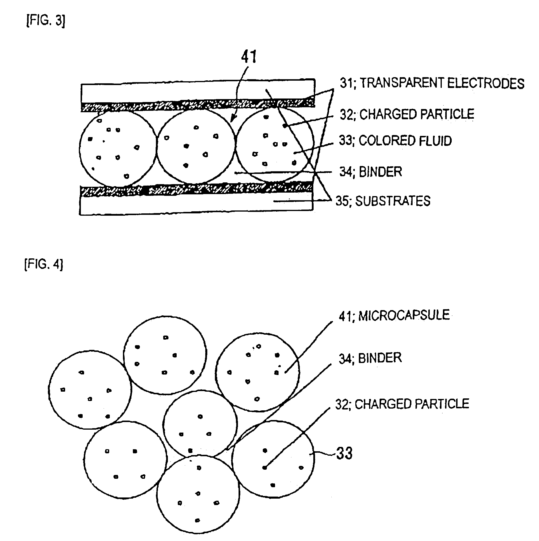
[0118]Titanium dioxide discharged particles 32 of about 0.3 μm were treated with a surfactant and were dispersed into a colored fluid 33 composed of dodecyl benzene colored with an anthraquinone blue dye. The colored fluid 33 containing the dispersed discharged particles 32 was added to an aqueous solution containing arabian gum and gelatin, and the mixture was stirred by an appropriate rotation to prepare substantially spherical microcapsules. The microcapsules 1a was classified into microcapsules 1a of 50 to 60 μm.

[0119]The microcapsules 1a and a silicon resin binder 5 were mixed in a ratio by weight of 95:5 to prepare a microcapsule dispersion, and the matching circuit was applied on a glass lower substrate 35a with a transparent electrode 31 using a coater. After the application, spacers with a thickness of 30 μm were arranged around the microcapsules 1a. A glass upper substrate with a tra...

Example

EXAMPLE 2

[0121]The electrophoretic display shown in FIGS. 1 and 13 was produced as follows:

[0122]Microcapsules 1a prepared as in EXAMPLE 1 and a binder 5 containing a silicon resin and water were mixed in a ratio by weight of 56:4:40 to prepare a microcapsule dispersion, and the microcapsule dispersion was applied on a lower substrate 35a similar to that in EXAMPLE 1 using a coater. After the application, the substrate was dried at 90° C. for 20 minutes, and a glass upper substrate with a transparent electrode 31 was bonded thereto to complete the electrophoretic display.

[0123]A photograph viewed from the display face side of the resulting electrophoretic display is shown in FIG. 7. FIG. 7 shows that microcapsules 1 in contact with the surface of the substrate at the display face side are contacted with the lower substrate 35a, and that adjoining microcapsules 1 and 1 are contacted with each other. This electrophoretic display was driven at 50 volts and the difference in brightness ...

Example

EXAMPLE 3

[0127]Using the electrophoretic display prepared in EXAMPLE 2, an electrophoretic display which can display-segments two-digit date was prepared and assembled into a wrist watch with date displaying, and a boosting circuit was assembled to drive the watch.

[0128]This display is superior to traditional one including a liquid crystal device in color brightness and appearance. Moreover, the device is about 30% superior to an electrophoretic display prepared by a traditional method in difference in brightness.


PUM


Abstract

An electrophoretic display comprising a plurality of microcapsules disposed between a pair of substrates, wherein each microcapsule comprises a capsule body containing an insulating fluid and charged particles dispersed in the fluid. The microcapsules are contacted with at least the substrate arranged at a display face side of the pair of substrates and each microcapsule has a flat surface at least at the display face side so that the substrate at the display face side is in face-to-face contact with the microcapsules. As a result, the proportion of the contact area of the substrate with the microcapsules increases compared with the traditional electrophoretic display, preventing uneven displaying and achieving increased contrast and high-quality displaying.

Description

CROSS-REFERENCE TO RELATED APPLICATIONS[0001]This application is a continuation-in-part of U.S. patent application Ser. No. 10 / 076,050 filed on Oct. 29, 2001 now abandoned, which claims priority to Japanese Patent Application 2001-326519, filed Oct. 24, 2001, and Japanese Patent Application 2000-329367, filed Oct. 27, 2000. The disclosures of the above applications are incorporated herein by reference in their entirety.BACKGROUND OF THE INVENTION[0002]The present invention relates to electrophoretic displays and electronic apparatuses provided with the electrophoretic displays.[0003]In recent years, portable information apparatuses have rapidly developed. Thin displays of low-power consumption are increasingly required. A variety of developments are attempted to meet these requirements. Liquid crystal displays have satisfied such requirements.[0004]The liquid crystal displays, however, still have unresolved problems, such as unsatisfactory visibility due to a viewing angle to the sc...

Claims


Application Information

Patent Timeline
IPC IPC(8): G02B26/00G09G3/34G02F1/167G02F1/16757G02F1/1679
CPCG02F1/167G02F1/16757G02F1/1679
Inventor KANBE, SADAO
Owner SEIKO EPSON CORP
Why Eureka
Try Eureka