Signal demodulation method and apparatus for reproducing data from received signal

a signal and demodulation method technology, applied in the field of demodulation methods and demodulation apparatuses for reproducing data, can solve problems such as decision boundary and error in received data, data errors on the reception side, and data errors on the receiving side, so as to ensure the decision margin and suppress the effect of data reproduced error

Inactive Publication Date: 2006-05-02
KOKUSA ELECTRIC CO LTD
View PDF9 Cites 6 Cited by
  • Summary
  • Abstract
  • Description
  • Claims
  • Application Information

AI Technical Summary

Benefits of technology

[0059]By doing so, a constant AGC gain is set and AGC processing is conducted even if there is a large received signal level difference generated at the time of switchover of the transmission antenna. And with the tap coefficients updated on the basis of the training signal of the pertinent received frame, automatic equalization processing of the received frame signal ...

Problems solved by technology

This results in a problem that data errors occur on the reception side.
In this situation, if there is noise on the transmission path, an equalization error, a received signal level variation, and so on, then the received signal exceeds the decision boundary, and even when the noise is added to the signal or the tran...

Method used


Image

  • Signal demodulation method and apparatus for reproducing data from received signal
  • Signal demodulation method and apparatus for reproducing data from received signal
  • Signal demodulation method and apparatus for reproducing data from received signal

Examples


second embodiment

[0091]a signal demodulation apparatus according to the present invention will now be described. In this embodiment, the gain setting of the AGC 2 is conducted in accordance with the received power calculated every frame of the received signal, in synchronism with each frame of the received signal. During the frame period of the received signal, the gain is made constant.

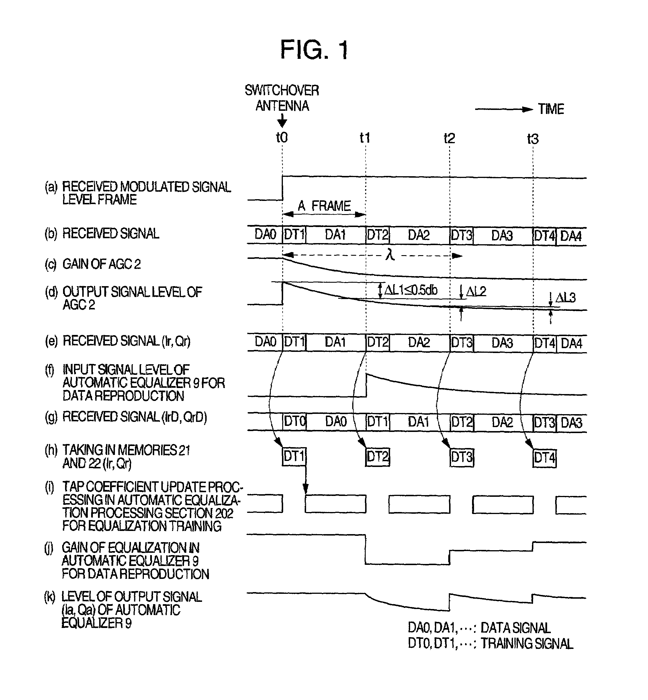
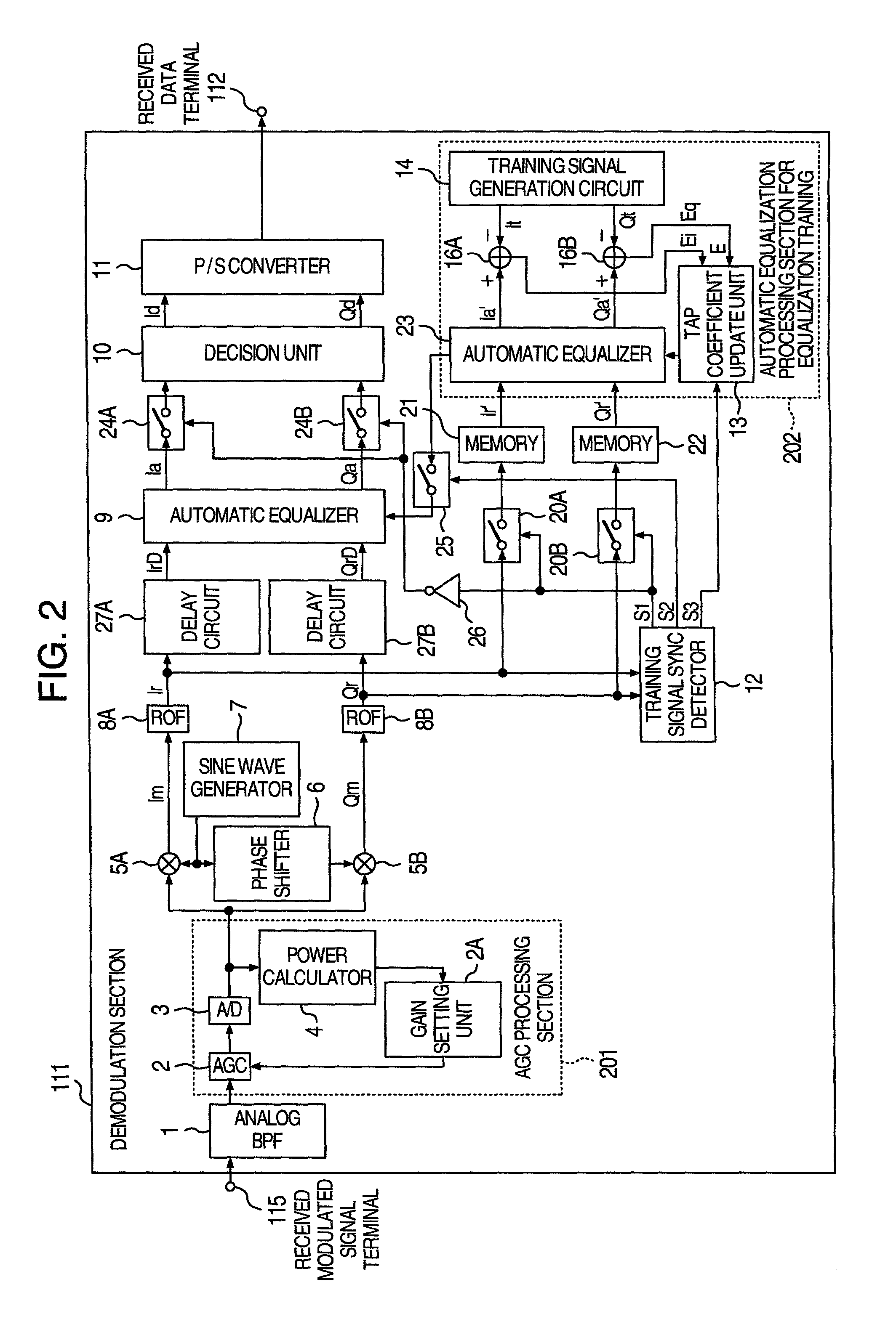
[0092]In the same way as the above-mentioned first embodiment of the present invention, such an example that the received signal level of the reception side is suddenly changed to become large by the antenna switchover of the transmission side will now be described by referring to FIGS. 3 and 4. FIG. 4 shows a configuration example of the demodulation section 111 that implements the second embodiment of the present invention. FIG. 3 is its signal timing chart. As shown in (a) of FIG. 3, the received signal level becomes high in a step form at time t0.

first embodiment

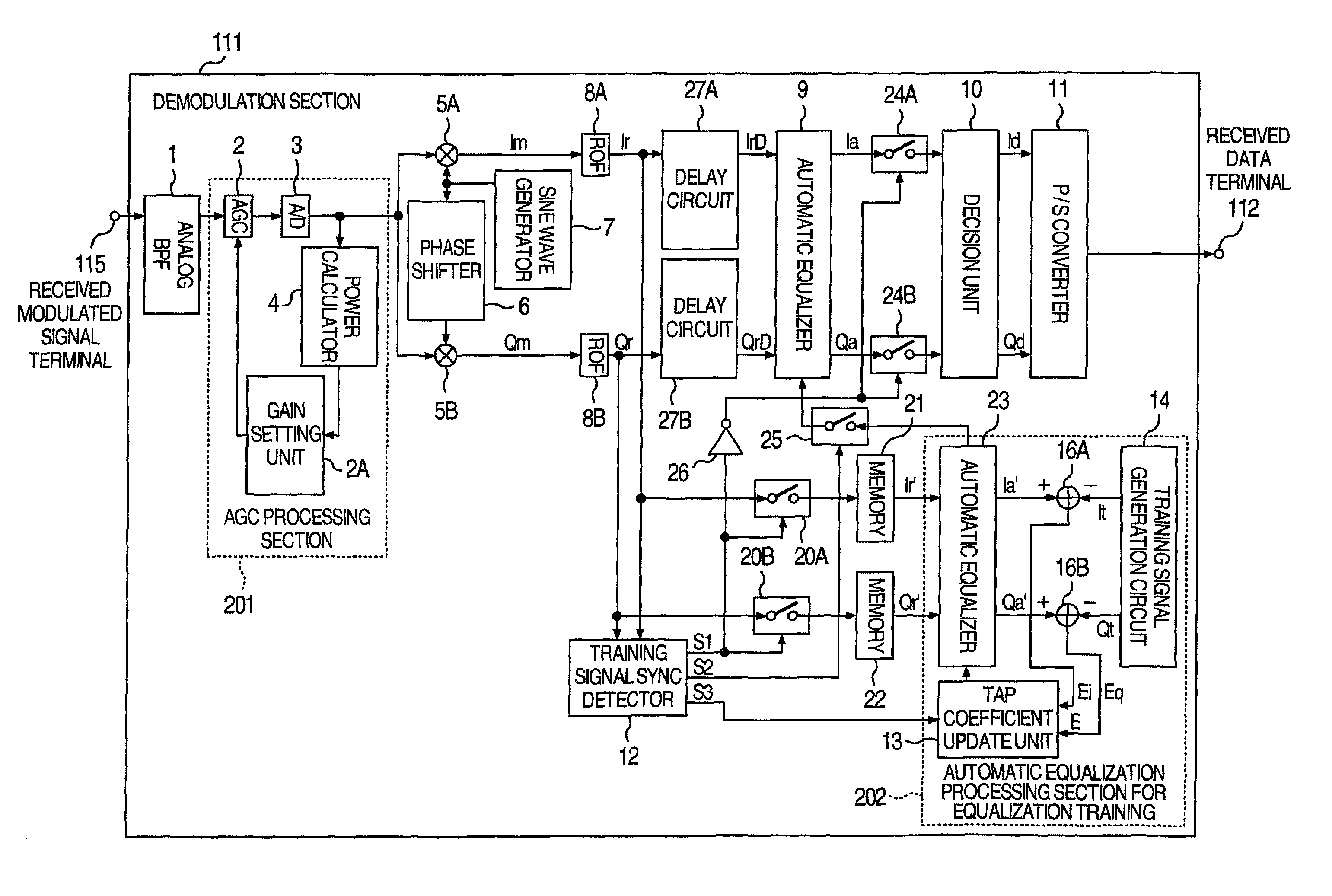
[0093]In the configuration of the demodulation section 111 of FIG. 4, a component denoted by the same character as that of FIG. 2, which shows the configuration of the demodulation section 111 of the first embodiment according to the present invention, has like function, and consequently description thereof will be omitted. However, numeral 17 in FIG. 4 denotes a training signal synchronization detector. In addition to the function of the training signal synchronization detector 12 shown in FIG. 2, the training signal synchronization detector 17 supplies a timing signal S4 to a gain setting unit 2A as a timing signal for setting the gain in the AGC 2, in synchronism to the head of a frame of the received signal.

[0094]As for operation of an AGC processing section 201, it calculates the received power corresponding to one frame of the received signal, and conducts gain setting according to the received power only at the head of the training signal of the subsequent frame. That is, on ...


PUM


Abstract

A demodulation method, and apparatus, for reproducing data from a received signal. The demodulation method includes the steps of: receiving a signal including a series of frames each containing a training signal for automatic equalization processing and a data signal; controlling an amplitude of the received signal by AGC processing so as to make the amplitude a predetermined level; conducting demodulation processing on the signal subjected to the AGC processing; periodically conducting automatic equalization processing so as to adapt the modulated signal to characteristics of the signal transmission path based on each training signal of the frame; and setting values of a time constant of the AGC processing and an update repetition period of the automatic equalization processing so as to satisfy a predetermined relation.

Description

CROSS-REFERENCE TO RELATED APPLICATION[0001]The present application relates to subject matters described in co-pending application Ser. No. 09 / 819,709 filed on Mar. 29, 2001 by Yoshihiro Kokuryo, et. al. and entitled “AUTOMATIC EQUALIZATION CIRCUIT AND RECEIVER CIRCUIT USING THE SAME.” The disclosures of this application is incorporated herein by reference.BACKGROUND OF THE INVENTION[0002]The present invention relates to a demodulation method, and demodulation apparatus for reproducing data that can reduce reproduced data errors caused by a received signal level variation that is incurred by switchover of an antenna of a transmission side or other causes in transmission of radio data using a radio wave from a mobile body such as in a helicopter or a vehicle, or a stationary body to a mobile body or a stationary body.[0003]In the case where data is radio-transmitted from a transmission apparatus (hereafter referred to as transmission side) mounted on a mobile body such as a helicopte...

Claims


Application Information

Patent Timeline
IPC IPC(8): H04L25/49H03D3/00H04L27/01H04B3/06H04B7/005H04B7/06H04L25/03H04L27/22H04L27/38
CPCH03D3/007H04L25/03133H04L27/3809H04W52/52H04L2025/03477H04L2025/0377H04L2025/0342
Inventor KOKURYO, YOSHIROKONDO, KUNIHIKOANDO, HIROYUKIHIROSE, NOBUO
Owner KOKUSA ELECTRIC CO LTD
Why Eureka
Try Eureka