This method allows calculating some properties of the interior of the object under test but resolution is generally poor.
The fact that the object is moderately absorbing to the radiation used for measurement puts a thickness limit to the probes that can be investigated.
For this case no feasible method is available today regarding the state of the art.
Method used
Image
Click on the blue label to locate the original text in one second.
Reading with bidirectional positioning of images and text.
Examples
first embodiment
[0097]FIG. 5a shows a first embodiment for determining the dielectric function in an object, such as a food product, to determine a physical property in the object, such as internal temperature without physically probing the object, during preparation of the object.
[0098]The flow starts in step 110, where a point in the object is selected. It is advantageous to select a point that has been used during the process of obtaining the ultrasound metric. The selected point corresponds to point 3 in equations 1–17.
[0099]The ultrasound radiation is thereafter focused on this point in step 111 and in step 112, the S-parameters S31 and S23 are measured, as described in more detail in connection with FIG. 6.
[0100]In step 113, a decision is made whether another point should be selected or not. If another point should be selected the flow is fed back to step 110, where a new point is selected before steps 111 and 112 are repeated. If not, the flow continues to step 114 where the matrix with the ...
second embodiment
[0102]FIG. 5b shows a second embodiment for determining the dielectric function in an object, such as a food product, to determine a physical property between two locations in the object, such as material properties, e.g. the presence of a brain tumor, without physically probing the object.
[0103]The flow starts in step 210, where a pair of points in the object is selected. It is advantageous to select points that have been used during the process of obtaining the ultrasound metric. The selected points correspond to point 3 and 4 in equations 1–17.
[0104]The ultrasound radiation is thereafter focused on both points in step 211 and in step 212, the S-parameters S31, S23, S41, S24, S4′1, S24′, S3′1 and S23′ are measured, as described in more detail in connection with FIG. 7.
[0105]The S-parameter S43, i.e. the damping between the selected points, is calculated in step 213. Point 3 acts as a virtual transmitter and point 4 functions as a virtual receiver in this embodiment.
[0106]The mean ...
PUM
Abstract
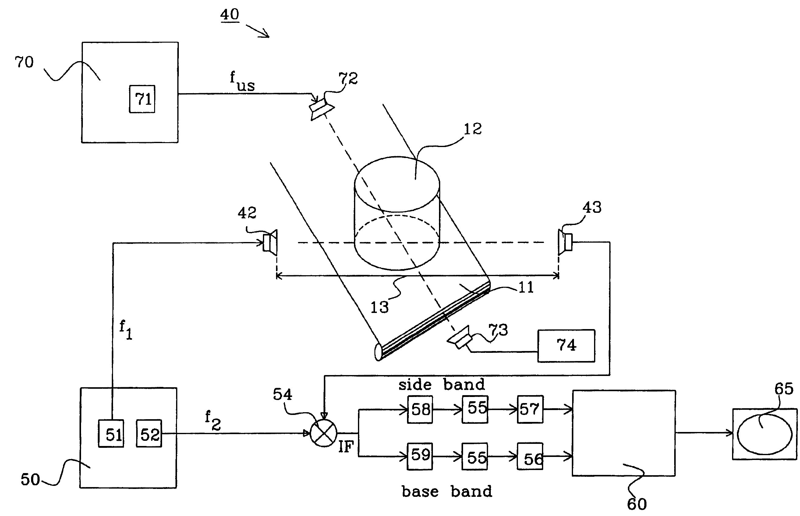
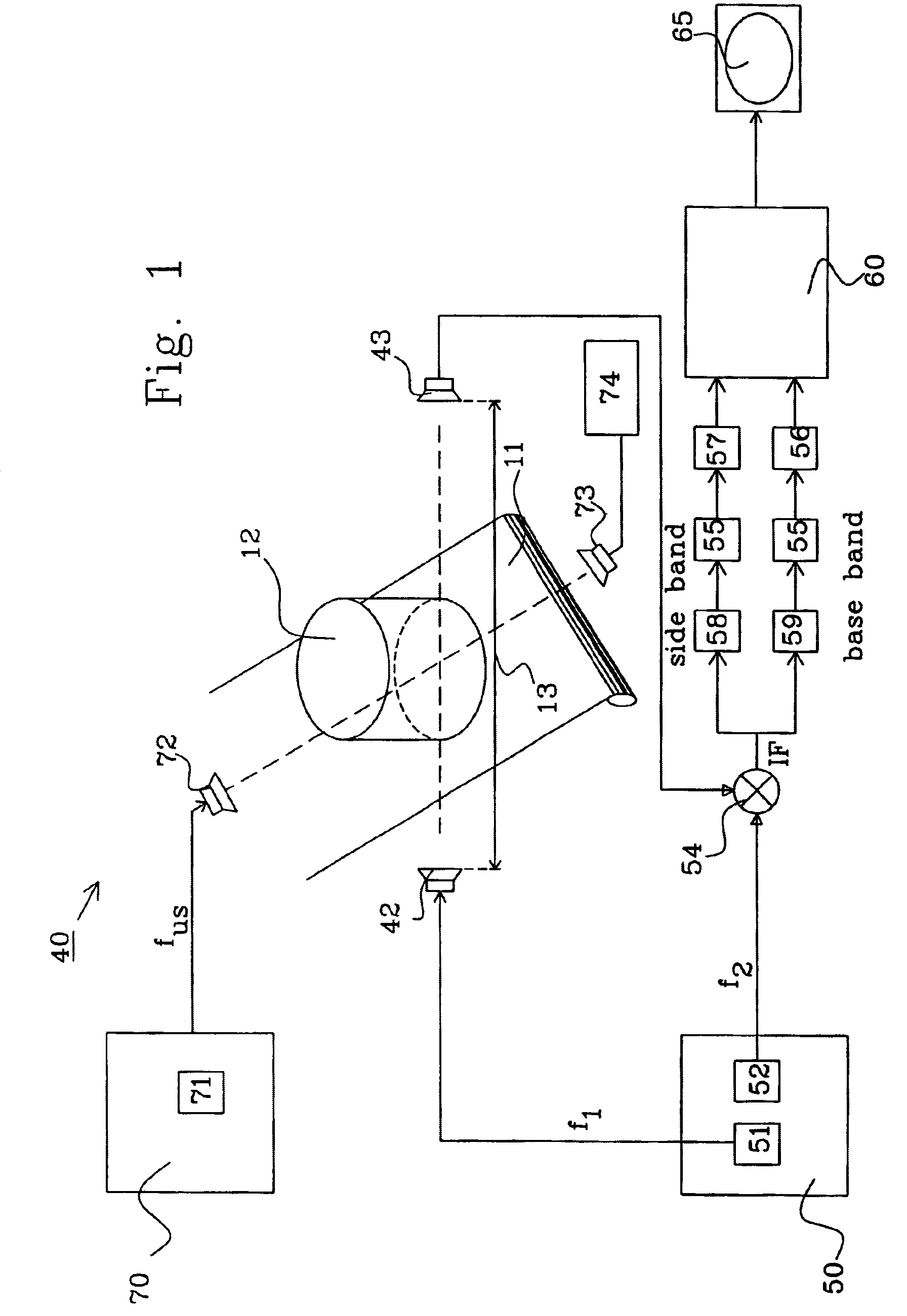
The present invention relates to an apparatus for determining a dielectric function in an object. The apparatus includes one transmit antenna for transmitting microwaveradiation through the object, and one receive antenna for receiving the transmitted microwaveradiation, one ultrasoundtransmitter for emitting ultrasoundradiation through the object to generate a density variation in the object, means to analyse the microwave radiation transmitted through the density variation to determine the acousto-electric interaction in the object, and a device to calculate the dielectric function in the object from the acousto-electric interaction. The invention also relates to a method for determining the dielectric function in an object.
Description
TECHNICAL FIELD[0001]The present invention relates to an apparatus for determining physical parameters, such as temperature or density, inside an object by determining the dielectric function of the object as defined in claim 1. The invention also relates to a method for determining the dielectric function inside an object as defined in claim 10, and an apparatus for determining the local distribution of temperature in a food product as defined in claim 15.BACKGROUND OF THE INVENTION[0002]In order to obtain information regarding temperature, density and other interior parameters of arbitrary objects without destroying, invading or dissecting the object, radiation(s) of various types are available to provide information that allow(s) to reconstruct the desired parameters.[0003]Choosing a specific type of radiation, there are four distinct cases that incorporate their proper implications on the choice of method of analysis. These are classified by two question areas:[0004]transparency...
Claims
Application Information
Patent Timeline
Application Date:The date an application was filed.
Publication Date:The date a patent or application was officially published.
First Publication Date:The earliest publication date of a patent with the same application number.
Issue Date:Publication date of the patent grant document.
PCT Entry Date:The Entry date of PCT National Phase.
Estimated Expiry Date:The statutory expiry date of a patent right according to the Patent Law, and it is the longest term of protection that the patent right can achieve without the termination of the patent right due to other reasons(Term extension factor has been taken into account ).
Invalid Date:Actual expiry date is based on effective date or publication date of legal transaction data of invalid patent.

