Drill bit and cutter having insert clusters and method of manufacture

a technology of insert clusters and drill bits, which is applied in the field of earth-moving bits, can solve the problems of reducing the width of the cutter, affecting the shape and design of the cutter element, and requiring considerable time, effort and expense, and achieving the effect of reducing the width

Inactive Publication Date: 2006-05-09
SMITH INT INC
View PDF63 Cites 32 Cited by
  • Summary
  • Abstract
  • Description
  • Claims
  • Application Information

AI Technical Summary

Benefits of technology

[0019]The aperture retaining the cluster of inserts is preferably a multilobed aperture. The aperture may be formed by forming intersecting bores into the cone steel such that the multilobed aperture is formed having a neck portion of reduced width disposed between the lobes. The bores forming the multilobed aperture may be formed parallel to one another or skewed and, likewise, may be generally perpendicular or not perpendicular to the cone surface in which they are formed. Varying the depth of bores, as well selecting appropriate angles for the bores, permits forming an aperture and retaining a cluster of inserts that may provide a cutting surface of desired surface area and shape that would not otherwise be possible due to space limitations within the cone steel.
[0025]The bits, rolling cone cutters, and insert clusters described herein provide opportunities for improvements in bit ROP and durability. In part, such opportunities are presented due to the ability to provide a relatively large cutting surface area provided by insert cluster without also requiring a correspondingly large socket that, in conventional bits employing conventional inserts may not be possible due to an insufficient volume of cone material between the socket and the sockets retaining adjacent inserts. Further, where employed, the use of different materials for different inserts within a cluster potentially offers enhanced ROP and longer bit life. These and various other characteristics and advantages potentially offered by the embodiments described herein will be readily apparent to those skilled in the art upon reading the following detailed description of the preferred embodiments, and by referring to the accompanying drawings.

Problems solved by technology

As is thus obvious, this process, known as a “trip” of the drill string, requires considerable time, effort and expense.
At the same time, however, the size, shape and design of a particular cutter element is also dependent upon, and many times compromised by, factors such as the location in the drill bit in which it is to be placed, the type of formation, and the element's vulnerability to the forces expected to be encountered.
Unfortunately, it is many times impossible to provide an insert with the cutting portion of the desired size due to limitations in the core steel available for retaining the insert's base.
More particularly, bores formed in the cone steel for retaining other inserts in the same row, as well as bores retaining inserts in other rows in the cone, limit the depth and diameter of a given hole.
In short, the limited volume of cone steel available for receiving and retaining the base portion of inserts has typically limited the size and shape of the cutting portion of the insert.
While providing the advantage of an increased cutting surface area, as compared to other conventional inserts, such inserts are more expensive to manufacture and are difficult to secure in the cone in a way that prevents rotation of the insert and misalignment of the cutting portion with the desired orientation.
This method of forming the slotted socket thus requires machining that, relative to merely boring holes into the cone steel, is more time consuming, expensive, and exacting.
Providing a slot-like socket capable of retaining the elongate, non-circular insert by interference fit is difficult to achieve.

Method used


Image

  • Drill bit and cutter having insert clusters and method of manufacture
  • Drill bit and cutter having insert clusters and method of manufacture
  • Drill bit and cutter having insert clusters and method of manufacture

Examples


Embodiment Construction

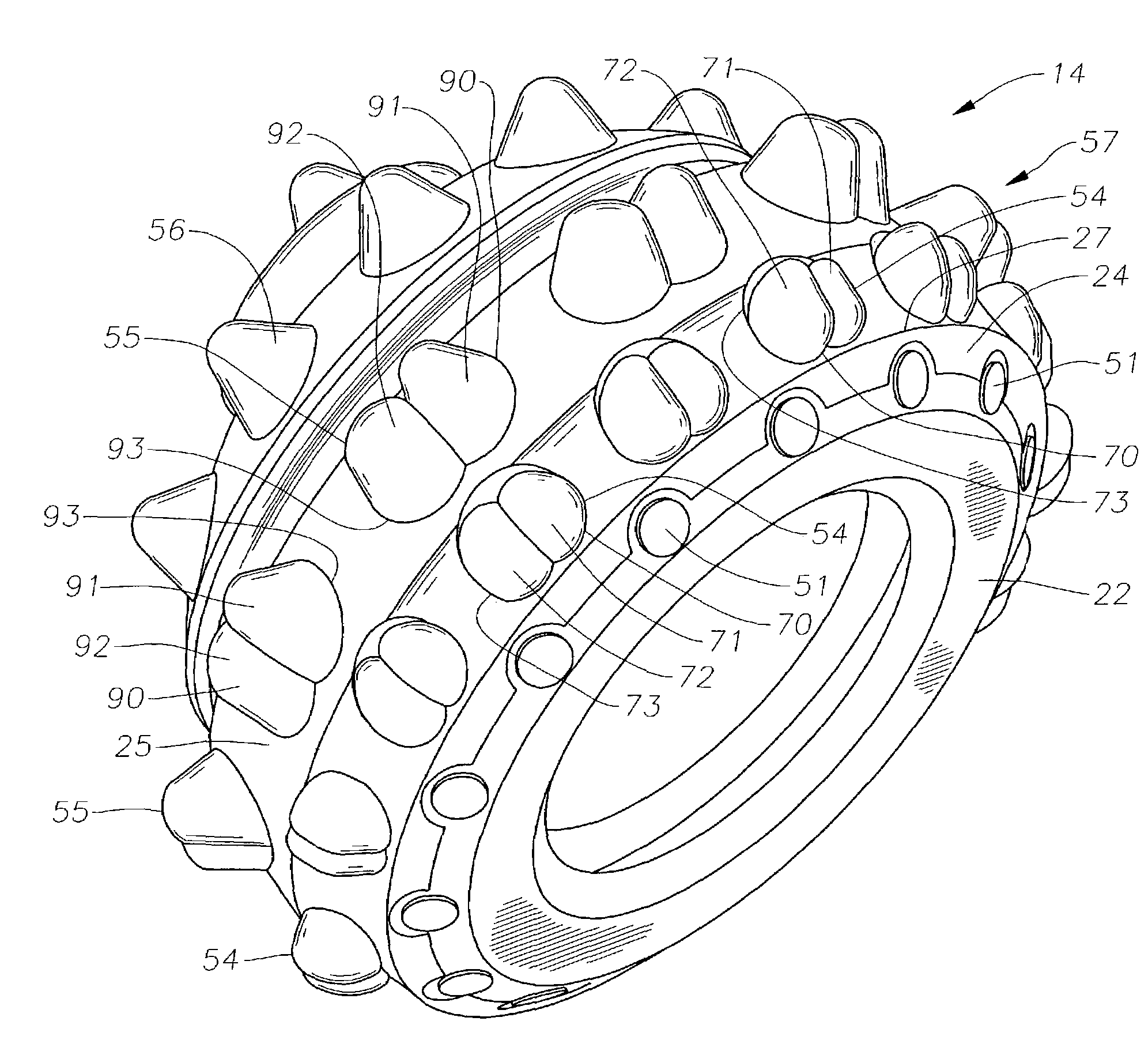
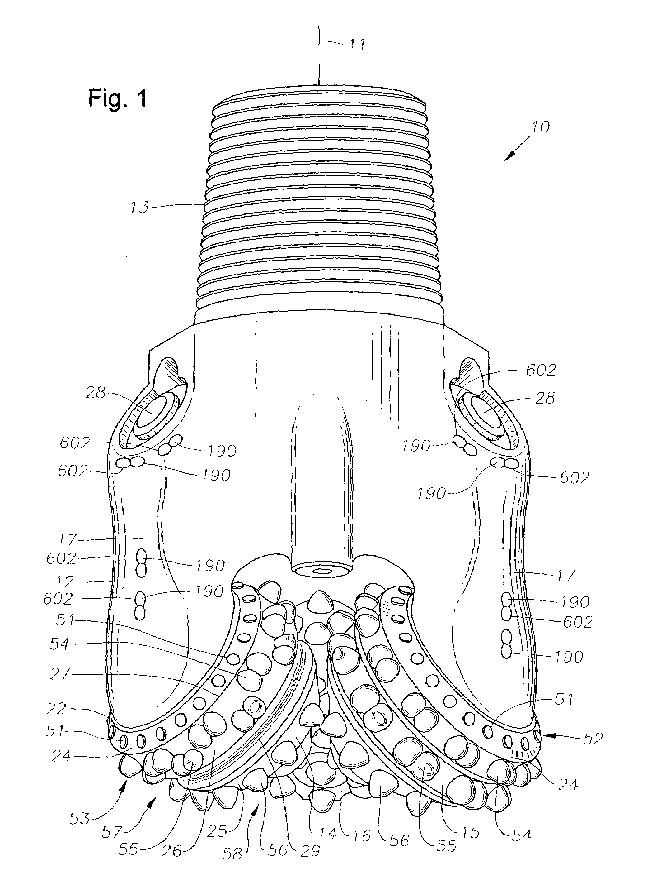
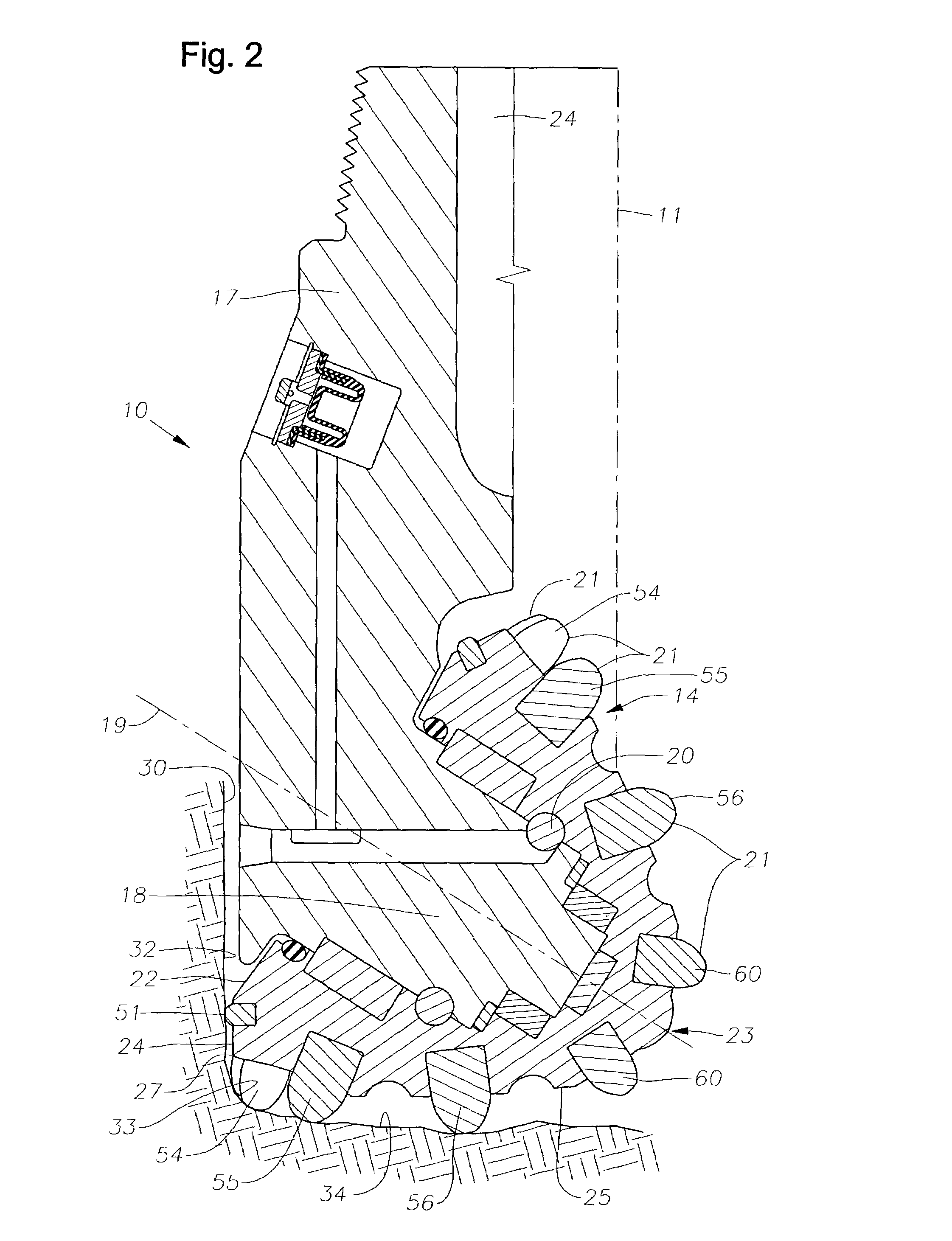
[0018]Preferred embodiments are disclosed for drill bits or other drilling apparatus with enhancements in cutter element design and in manufacturing methods that provide the potential for enhancing bit ROP and increased bit life. The embodiments disclosed include a drill bit including at least one rolling cone cutter, the cutter including an aperture and a cluster of discrete cutting inserts secured together in the same aperture. The cluster of cutting inserts may include two, three, or a larger number of inserts. The inserts in a cluster may have differing sizes and shapes and may be embedded within the cone steel to differing depths and extend beyond the cone steel to differing heights. Likewise, the inserts in a cluster may be made of, or coated with, materials that differ in hardness, wear resistance and toughness, so as to particularly tailor the inserts of the cluster to optimally perform and best withstand the type of cutting duty that the insert will experience. Thus, for ex...


PUM

PropertyMeasurementUnit
sizesaaaaaaaaaa
depthsaaaaaaaaaa
heightsaaaaaaaaaa

Abstract

Disclosed is a rolling cone cutter and drill bit employing multiple inserts retained as a cluster in an aperture in the cone cutter. Apertures in which the insert clusters are retained are multilobed apertures formed by intersecting bores formed in the cone steel. The apertures may also be created by forming spaced apart bores and milling regions of the cone steel that extends between the bores. The inserts in a cluster may be retained within the aperture to differing depths, may extend above the cone steel to differing extension lengths, and may have cutting portions having a variety of shapes. The inserts in a cluster may be made of different materials in order to optimize cutting duty. The bores forming the multilobed aperture may be parallel or skewed, and may create an aperture having a multilevel bottom surface so as to permit the insertion of an insert having a relatively large cutting surface in instances when the cone design would not otherwise permit the use of a cylindrical insert of the desired diameter.

Description

CROSS-REFERENCE TO RELATED APPLICATIONS[0001]Not Applicable.STATEMENT REGARDING FEDERALLY SPONSORED RESEARCH OR DEVELOPMENT[0002]Not Applicable.BACKGROUND OF THE INVENTION[0003]1. Field of the Invention[0004]The invention relates generally to earth-boring bits used to drill a borehole for the ultimate recovery of oil, gas or minerals. More particularly, the invention relates to rolling cone rock bits and to an improved cutting structure for such bits. Still more particularly, the invention relates to enhancements in cutter elements and in manufacturing techniques for cutter elements, rolling cone cutters and drill bits.[0005]2. Description of the Related Art[0006]An earth-boring drill bit is typically mounted on the lower end of a drill string and is rotated by revolving the drill string at the surface or by actuation of downhole motors or turbines, or by both methods. With weight applied to the drill string, the rotating drill bit engages the earthen formation and proceeds to form ...

Claims


Application Information

Patent Timeline
Patent Type & Authority Patents(United States)
IPC IPC(8): E21B10/16E21B10/52
CPCE21B10/52B23P15/28
Inventor YONG, ZHOUDAVIES, PETER M.PENKA, JR., HUBERT W.BUFORD, ERNEST L.
Owner SMITH INT INC
Why Eureka
Try Eureka