Mass spectrometer

a mass spectrometer and mass spectrometer technology, which is applied in the direction of instruments, particle separator tube details, separation processes, etc., can solve the problems of reducing not being best suited to ionising highly polar analytes, and not being particularly suited to analysing mixtures containing both low and high polar analytes, so as to reduce the intensity of ion signal for highly polar or ionic analytes

Active Publication Date: 2006-05-09
MICROMASS UK LTD
View PDF5 Cites 41 Cited by
  • Summary
  • Abstract
  • Description
  • Claims
  • Application Information

AI Technical Summary

Benefits of technology

[0033]Preferably, the response of a sample in both the first and second modes may be used to help determine the polarity of the sample. This information may be used to assist in identifying the sample.

Problems solved by technology

However, highly polar or ionic analytes are more commonly analysed by Electrospray Ionisation (“ESI”) ion sources than by APCI ion sources since a problem with conventional APCI ion sources is that when they are used to ionise highly polar analyte molecules the ion signal is observed to decrease as the corona voltage or current is increased.
Therefore, although conventional APCI ion sources are suited to ionising low to moderately polar analytes they are not best suited to ionising highly polar analytes.
Another particular problem with conventional APCI ion sources is that they are also not particularly suited to analysing a mixture containing both low to moderately polar analytes and also highly polar analytes since the different types of analytes require different corona current settings for optimal ionisation.
As will be appreciated such an approach therefore results in a doubling of the total analysis time and also a doubling of the total sample consumption.
Both of these increases are problematic.
The increase in sample consumption is particularly problematic if only a very small amount of sample is available for analysis (which is often the case).

Method used


Image

  • Mass spectrometer
  • Mass spectrometer
  • Mass spectrometer

Examples


Embodiment Construction

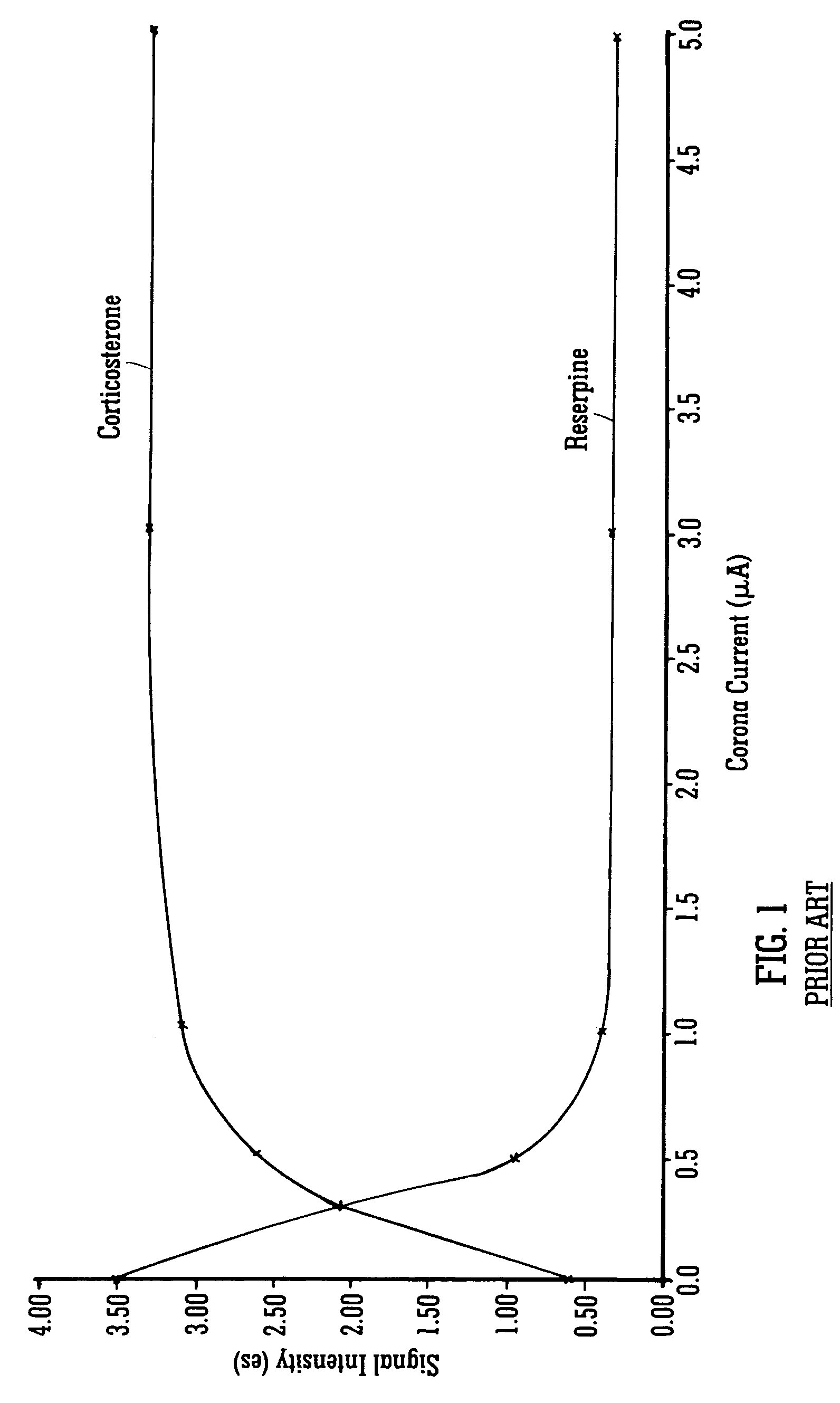
[0047]Referring to FIG. 1, this figure shows how the ion signal intensity varies as a function of the current applied to a corona needle of a conventional Atmospheric Pressure Chemical Ionisation (“APCI”) ion source for two different analytes. As can be seen from FIG. 1, the ion signal intensity for a low to moderately polar sample (i.e. Corticosterone) increases relatively rapidly and then plateaus at a certain point as the current applied to the corona needle is further increased. The initial increase in ion signal intensity is believed to be due to the ion source producing more reagent ions as the current applied to the corona needle is increased. The increased number of reagent ions interact with the analyte molecules emerging from the heated tube and hence more analyte ions are produced. Accordingly, an increased number of analyte ions are then subsequently mass analysed and hence an increase in the ion signal intensity is observed.

[0048]It can also be seen from FIG. 1 that inc...


PUM


Abstract

An Atmospheric Pressure Chemical Ionisation ion source is disclosed wherein the current applied to a corona needle 2 is repeatedly varied between two or more settings during a single experimental run or acquisition. Two or more separate sets of mass spectral or mass analysed data are obtained. The ion source in one embodiment comprises a heated tube 1 arranged to discharge gas and analyte into a housing 7 enclosing corona needle 2. The housing 7 comprises a gas outlet port 3 via which analyte ions exit. According to another embodiment the corona needle does not have to be enclosed within a housing.

Description

CROSS REFERENCE TO RELATED APPLICATIONS:[0001]This application claims benefit of U.S. Provisional Application No. U.S. 60 / 470,865 filed May 16, 2003 and United Kingdom application GB 0310696.9 filed May 9, 2003. The contents of each of the aforementioned applications are hereby expressly incorporated herein by reference in their entirety.STATEMENT ON FEDERALLY SPONSORED RESEARCH[0002]N / AFIELD OF THE INVENTION[0003]The present invention relates to a mass spectrometer comprising an ion source. The preferred embodiment relates to a mass spectrometer comprising an Atmospheric Pressure Chemical Ionization (“APCI”) ion source.BACKGROUND OF THE INVENTION[0004]Chemical ionization involves the transfer of charged species from reagent ions to analyte molecules to produce analyte ions that can be subsequently mass analyzed. The charged species most commonly formed in positive ion mode is the adduct between an analyte molecule and positive hydrogen ions (H+).[0005]Chemical ionization conducted ...

Claims


Application Information

Patent Timeline
Patent Type & Authority Patents(United States)
IPC IPC(8): H01J49/10
CPCH01J49/168
Inventor BAJIC, STEVEBATEMAN, ROBERT HAROLD
Owner MICROMASS UK LTD
Why Eureka
Try Eureka