

Piezoelectric acoustic transducer
- Summary
- Abstract
- Description
- Claims
- Application Information
AI Technical Summary
Benefits of technology
Problems solved by technology
Method used
Image

Examples
Embodiment Construction
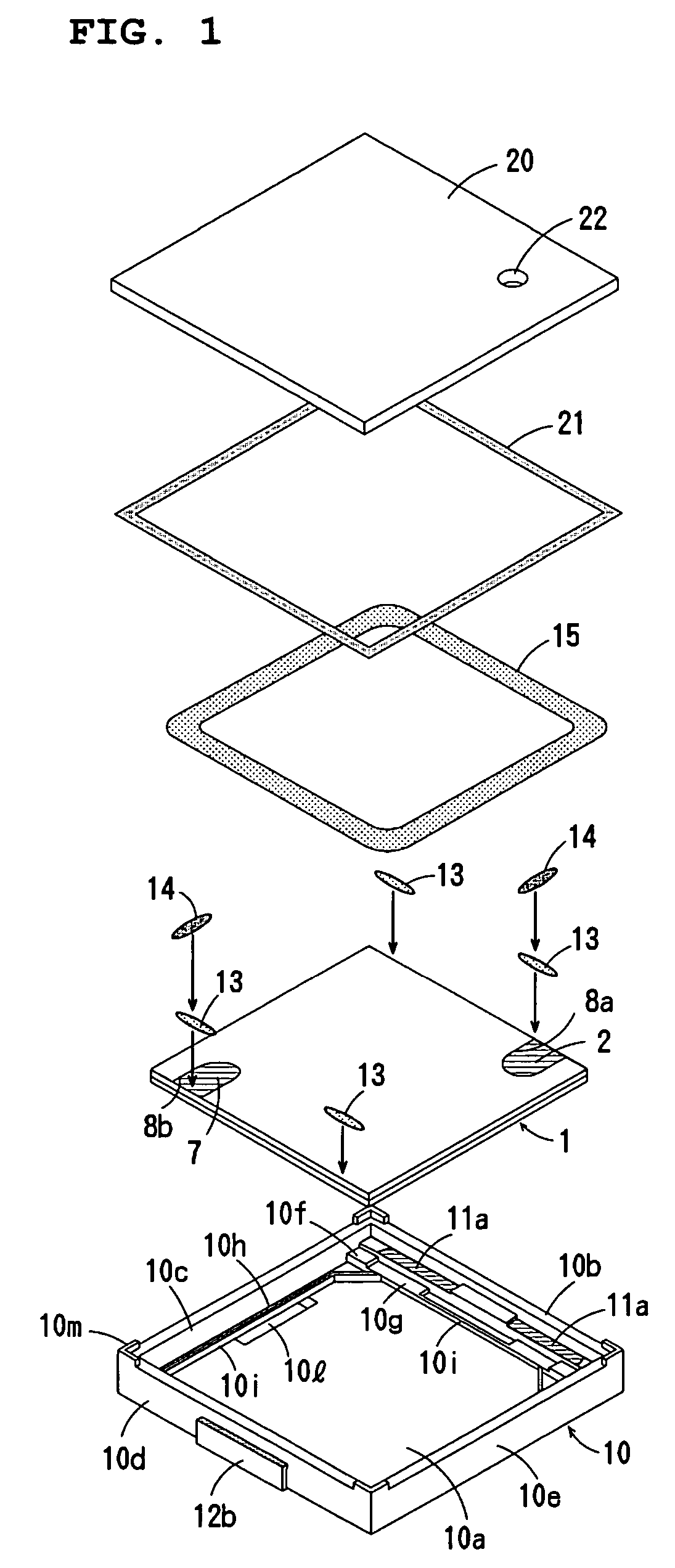
[0038]FIG. 1 shows a surface mounting piezoelectric type electroacoustic transducer according to a first preferred embodiment of the present invention.
[0039]The electroacoustic transducer of this preferred embodiment is suitable for use as piezoelectric receiver in which the operating frequency ranges are wide. The electroacoustic transducer is provided with a piezoelectric vibrating plate 1 having a laminated structure, a case 10, and a lid 20. The case 10 and the lid 20 define a box.
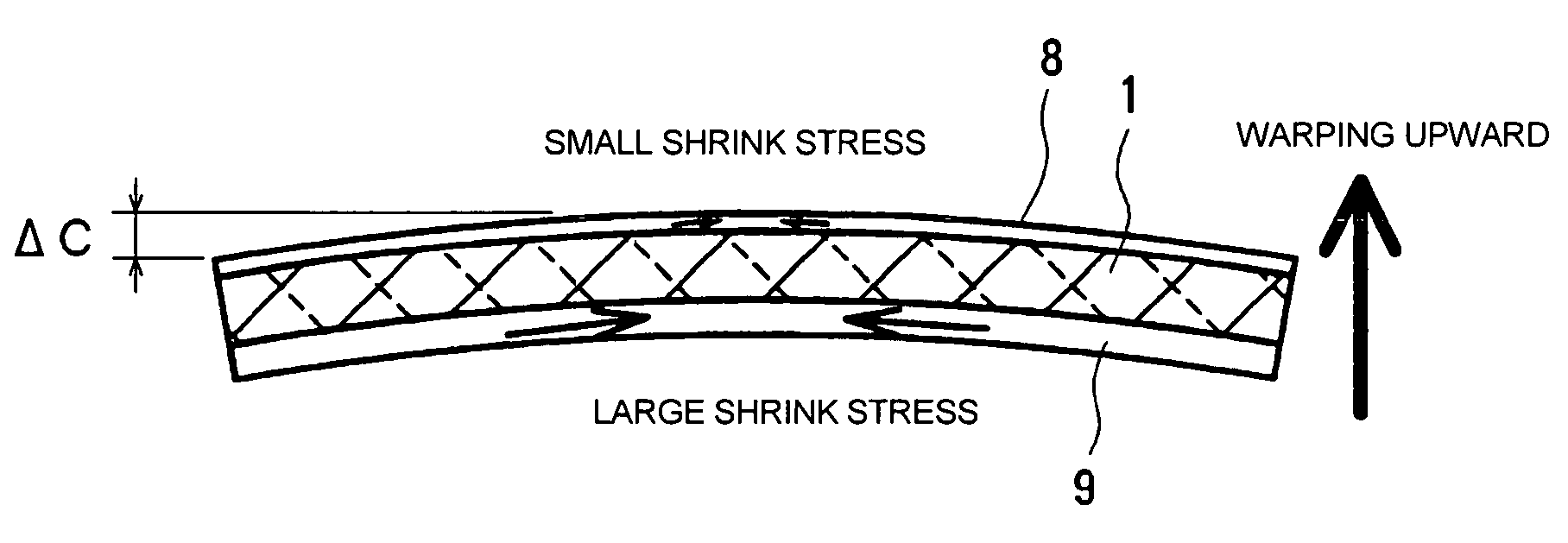
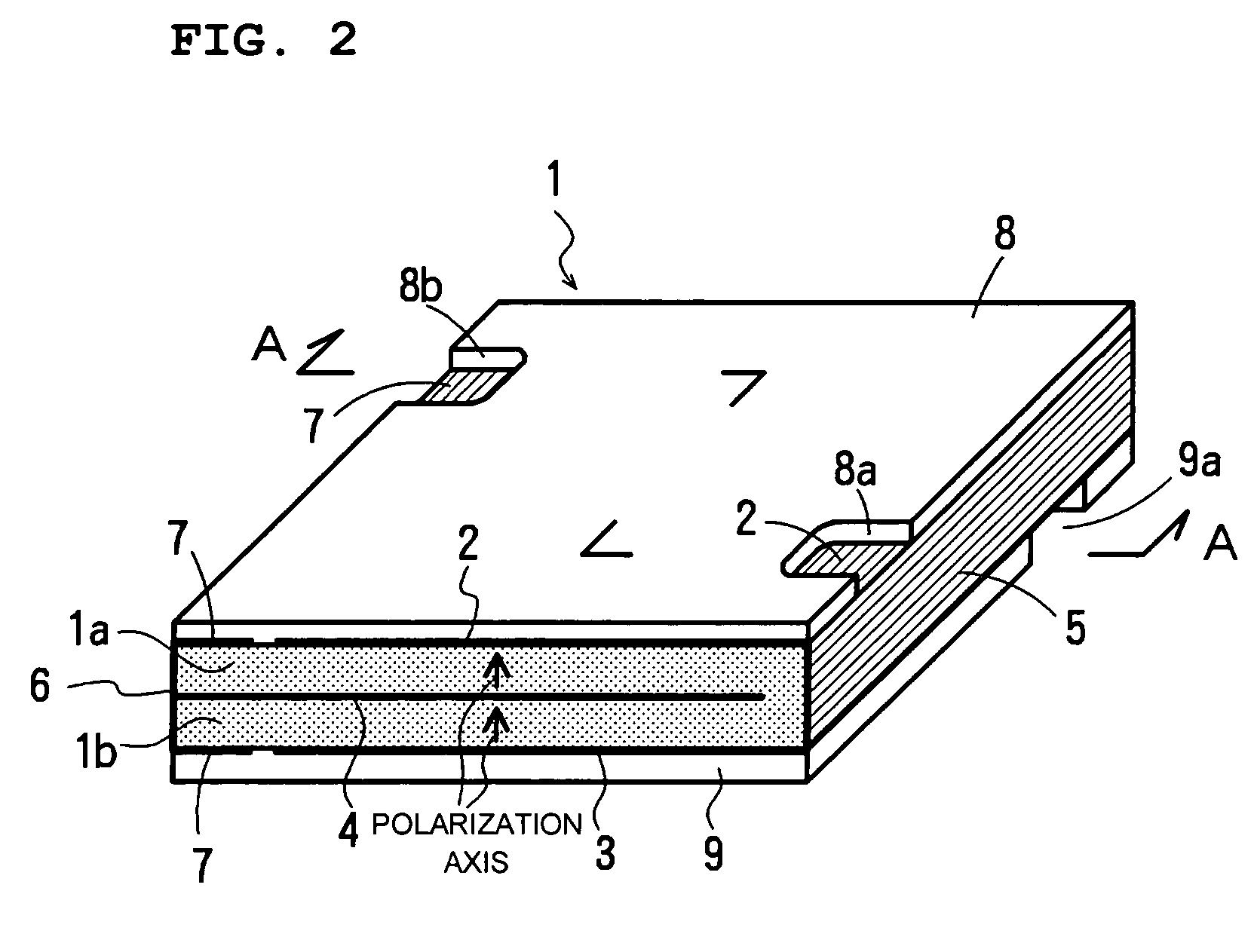
[0040]The vibrating plate 1 is preferably formed by laminating two piezoelectric ceramic layers 1a and 1b to each other as shown in FIGS. 2 and 3. Main-surface electrodes 2 and 3 are provided on the main surfaces on the front and back sides of the vibrating plate 1, respectively. An internal electrode 4 is provided between the ceramic layers 1a and 1b. The two ceramic layers 1a and 1b are polarized in the same thickness direction of the plate 1, as shown by bold line arrows in FIG. 2. The lengths of th...
PUM
 Abstract
Description
Claims
Application Information