Organic electroluminescent device having wiring lines under the partition walls and electronic apparatus using the same

a technology of electroluminescent devices and partition walls, which is applied in the direction of instruments, discharge tubes luminescnet screens, static indicating devices, etc., can solve the problems of reducing the aperture ratio, power consumption, and thick wiring lines for supplying electric current to the electrodes, so as to reduce the manufacturing cost and prolong the product life , the effect of high performan

Inactive Publication Date: 2006-05-09
ELEMENT CAPITAL COMMERCIAL CO PTE LTD
View PDF25 Cites 22 Cited by
  • Summary
  • Abstract
  • Description
  • Claims
  • Application Information

AI Technical Summary

Benefits of technology

[0046]According to the present invention, it is possible to configure a compact electronic apparatus having a high performance display part, and to further reduce the manufacturing cost and extend the product lifetime.

Problems solved by technology

However, in conventional organic EL devices, when forming display devices having a large screen, it is necessary to make wiring lines for supplying electric current to the electrodes thick because the power consumption increases.
In conventional organic EL devices which are display devices formed to have a large screen and in which the light transmitted through a substrate is used as display light, there occurs a problem in that the aperture ratio, expressed as the ratio of the area of a light-emitting region to that of a display region, decreases.
As a result, there is a problem in that the product lifetime is reduced.
Accordingly, the conventional organic EL device has a problem in that the manufacturing process is complicated due to the formation of the auxiliary electrodes and the manufacturing cost therefore increases.
The area occupied by the picture frame with respect to the whole area of the substrate is not negligible, and therefore, there is a problem in that the organic EL device tends to because larger and more expensive.

Method used


Image

  • Organic electroluminescent device having wiring lines under the partition walls and electronic apparatus using the same
  • Organic electroluminescent device having wiring lines under the partition walls and electronic apparatus using the same
  • Organic electroluminescent device having wiring lines under the partition walls and electronic apparatus using the same

Examples


Embodiment Construction

[0053]An organic EL device according to a preferred embodiment of the present invention will be described below with reference to the accompanying drawings.

[0054](Structure)

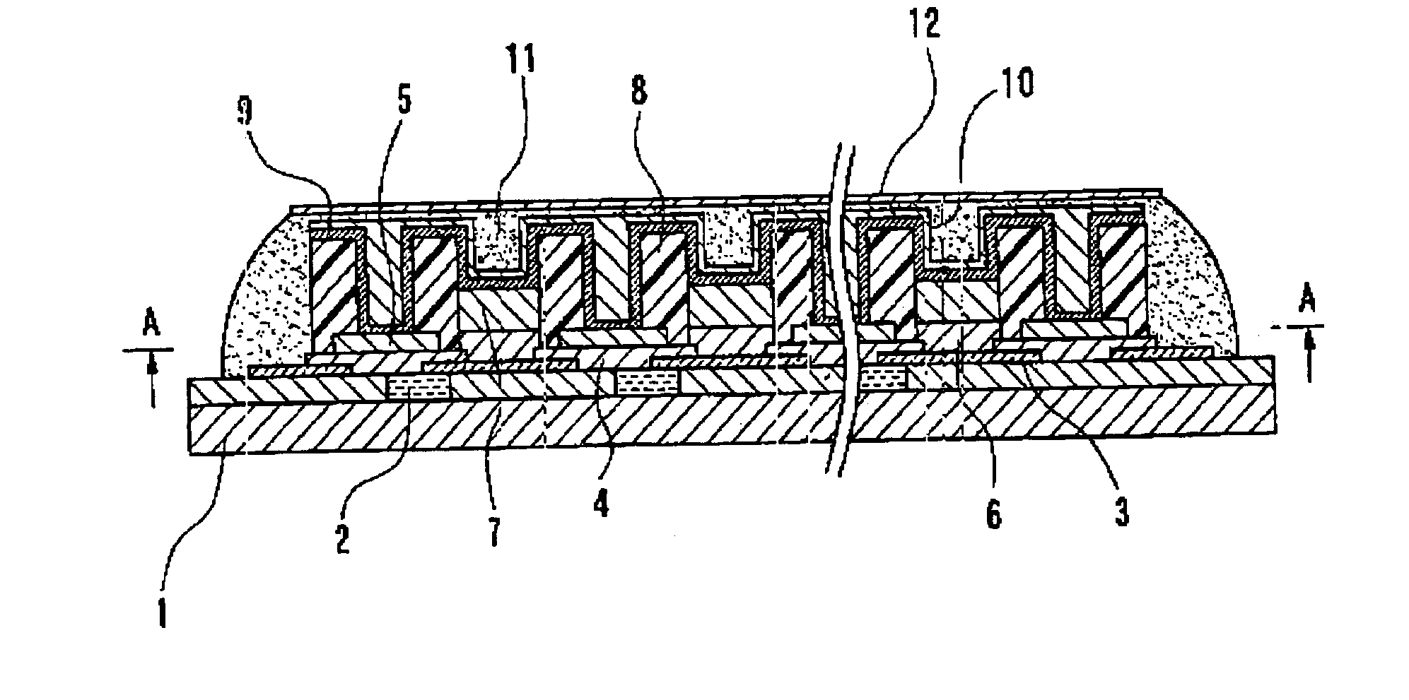
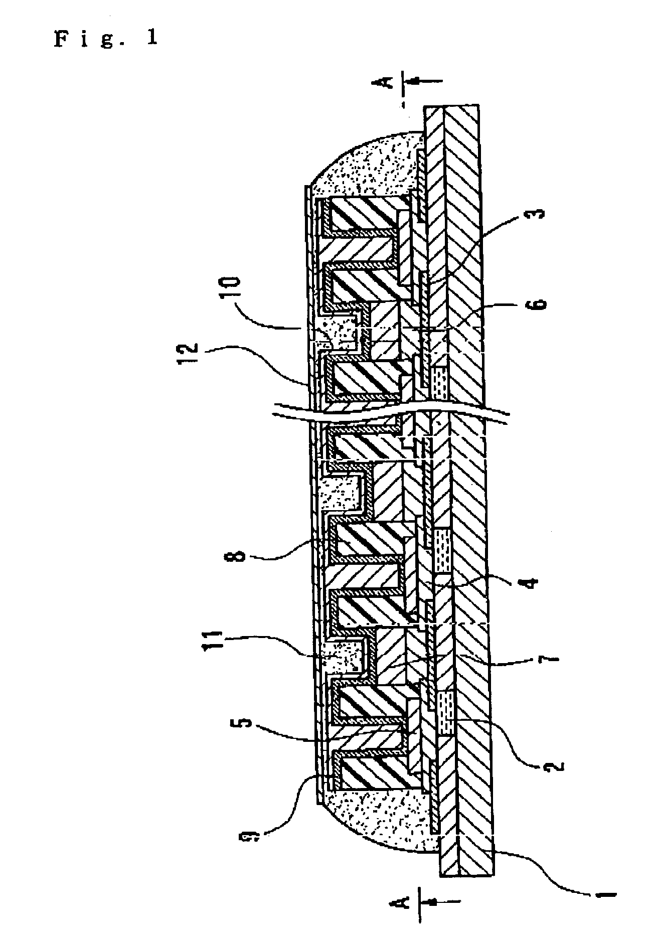
[0055]FIG. 1 is a cross-sectional view of essential parts illustrating an organic EL device according to a preferred embodiment of the present invention. The organic EL device is a sealing-side light emission type organic EL device, which has a structure in which light is emitted from a sealing substrate 12. Moreover, the organic EL device can also be applied to a substrate-side light emission type organic EL device, which has a structure in which light is emitted from a substrate 1.

[0056]The organic EL device has the substrate 1, light-emitting layers (EL layers) 7 made of an organic EL material, which is provided at one side of the substrate 1 and sandwiched between pairs of cathodes (first electrodes) 9 and anodes (second electrodes) 3, hole-injection layers (transport layers) 6, and a sealing substrate 12. He...


PUM

PropertyMeasurementUnit
organicaaaaaaaaaa
electroluminescentaaaaaaaaaa
transparentaaaaaaaaaa

Abstract

The invention provides an organic electroluminescent device, a method of manufacturing the organic electroluminescent device, and an electronic apparatus in which it is possible to make an entire display device compact as well as to reduce the manufacture cost. An organic electroluminescent device includes organic electroluminescent elements that each have a light-emitting layer between an anode and a cathode and that are formed on a substrate. The device includes lead-out wiring lines that are electrically connected to the cathodes.

Description

BACKGROUND OF THE INVENTION[0001]1. Field of Invention[0002]The present invention relates to an organic electroluminescent device, a method of manufacturing the organic electroluminescent device, and an electronic apparatus.[0003]2. Description of Related Art[0004]Conventionally, an organic electroluminescent (hereinafter, simply referred to as EL) devices have been considered for use as display means in portable apparatuses such as mobile phones or personal computers. In organic EL devices, a light-emitting layer (organic EL layer) is provided between two opposing electrodes, electric current flows between the electrodes, and the light emitted from the light-emitting layer is used as display light. Also, by providing a plurality of light-emitting layers on a plane, and by driving pixels each consisting of a set of one light-emitting layer and the electrodes, it is possible to configure a display apparatus that can display any image.SUMMARY OF THE INVENTION[0005]However, in conventi...

Claims


Application Information

Patent Timeline
Patent Type & Authority Patents(United States)
IPC IPC(8): H01L51/50H05B33/06H01L27/12H01L27/32H01L51/00H01L51/30H01L51/52H05B33/04H05B33/10H05B33/12H05B33/22
CPCH01L27/3246H01L27/3276H01L51/5228H01L27/12H01L51/0035H01L51/0038H01L51/0059H01L51/0078H01L51/0081H01L51/0036H10K59/122H10K85/114H10K85/113H10K85/111H10K59/131H10K85/631H10K85/311H10K85/324H10K50/824H05B33/06
Inventor KOBAYASHI, HIDEKAZU
Owner ELEMENT CAPITAL COMMERCIAL CO PTE LTD
Why Eureka
Try Eureka