Interlaced delay-locked loops for controlling memory-circuit timing

a delay-locked loop and memory-circuit technology, applied in the direction of pulse automatic control, pulse technique, multiple input and output pulse circuits, etc., can solve the problems of increasing the difficulty of design delay-locked loops which produce signals with smaller delays, adding a significant amount of circuitry, and conventional delay elements only reliably providing a minimum delay of about 100 picoseconds

Inactive Publication Date: 2006-05-09
ROUND ROCK RES LLC
View PDF19 Cites 9 Cited by
  • Summary
  • Abstract
  • Description
  • Claims
  • Application Information

AI Technical Summary

Problems solved by technology

As memory circuits have become faster, it has become increasingly difficult to design delay-locked loops which produce signals with smaller and smaller delays relative to a clock signal, such as the data clock.
This is because conventional delay elements can only reliably provide a minimum delay of about 100 picoseconds (one-tenth of one billionth of a second.)
Unfortunately, this interpolation approach not only adds a significant amount of circuitry to the basic delay-locked loop, but also increases power consumption considerably.

Method used


Image

  • Interlaced delay-locked loops for controlling memory-circuit timing
  • Interlaced delay-locked loops for controlling memory-circuit timing
  • Interlaced delay-locked loops for controlling memory-circuit timing

Examples


Embodiment Construction

[0027]The following detailed description, which references and incorporates FIGS. 1–11, describes and illustrates specific embodiments of the invention. These embodiments, offered not to limit but only to exemplify and teach the concepts of the invention, are shown and described in sufficient detail to enable those skilled in the art to implement or practice the invention. Thus, where appropriate to avoid obscuring the invention, the description may omit certain information known to those of skill in the art.

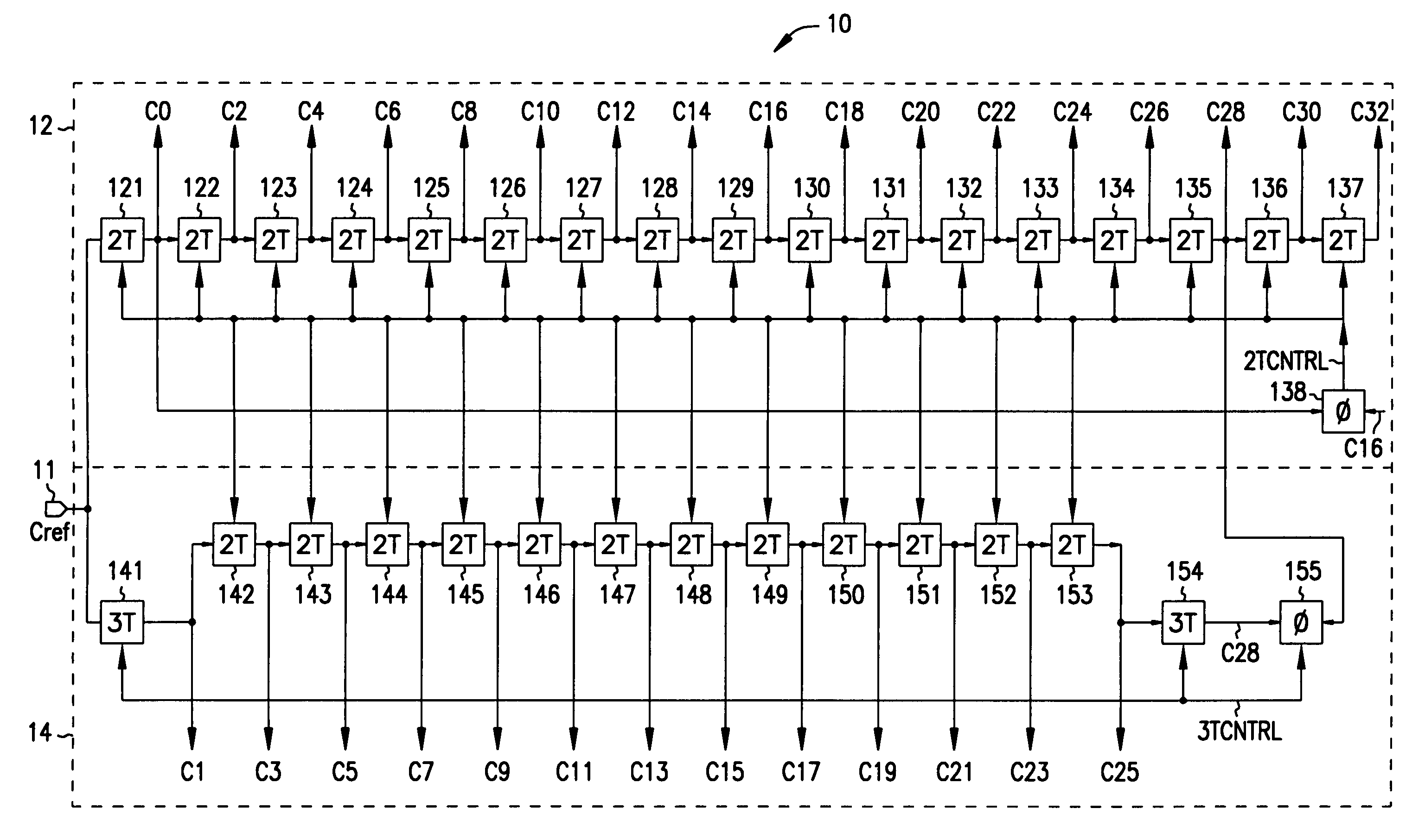
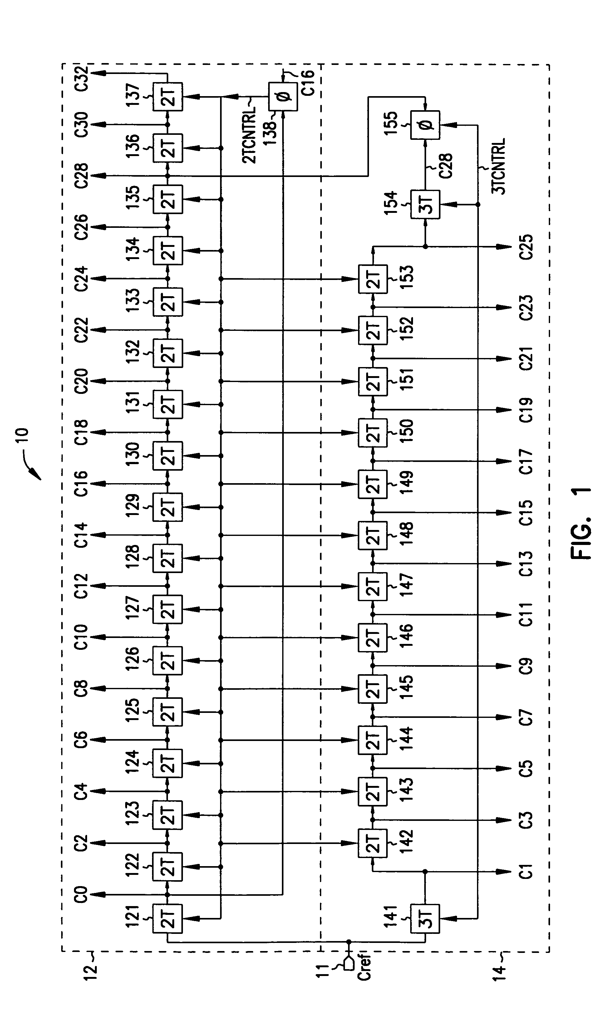
[0028]FIG. 1 shows a block diagram of an exemplary clock-generation circuit 10 embodying concepts of the present invention. Circuit 10 includes an input terminal or node 11 for receiving an input (reference) clock signal Cref, and two interlaced delay locked loops 12 and 14 for providing a set of clock signals delayed a multiple number of delay periods T relative reference clock signal Cref. T represents a desired time delay which generally requires use of interpolation circuitr...


PUM


Abstract

For control, some memory circuits use a delay-locked loop to generate a set of signals, each delayed a different amount relative a reference signal. However, as circuits get faster and faster, conventional delay-locked loops require use of extra interpolation circuitry to generate smaller delays, and thus consume considerable power and circuit space. Accordingly, the inventor devised a circuit which interlaces and synchronizes two delay-locked loops, each including a number of controllable delay elements linked in a chain. In one embodiment, the first loop produces a sequence of clock signals delayed an even number of delay periods relative a reference clock signal, and the second loop produces a sequence of clock signals delayed an odd number of delay periods relative the reference clock signal. In addition, the first and second loops are synchronized.

Description

[0001]This application is a Continuation of U.S. application Ser. No. 09 / 259,625, filed Feb. 26, 1999, now U.S. Pat. No. 6,777,995, which is incorporated herein by reference.TECHNICAL FIELD[0002]The present invention concerns memory circuits and clock-generation circuits which include delay-locked loops for controlling memory circuits.BACKGROUND OF THE INVENTION[0003]Memory circuits are vital components in computers and other electronic systems which require data storage. A typical memory circuit is an interconnected network of millions of microscopic memory cells, each of which stores an electric charge representing a one or zero data bit. The memory cells are usually arranged into rows and columns, with each cell having a unique address based on its row and column position.[0004]Memory operations, usually initiated by a computer processor, include writing and reading the memory cells. In writing, sometimes called recording or programming, the processor sends command signals specif...

Claims


Application Information

Patent Timeline
Patent Type & Authority Patents(United States)
IPC IPC(8): H03H11/26H03K5/13H03K5/135H03K5/26H03L7/07H03L7/081H03L7/089H03L7/10
CPCH03K5/135H03K5/26H03L7/07H03L7/0805H03K5/133H03L7/0896H03L7/10H03L7/0812H03L2207/14
Inventor HARRISON, RONNIE M.
Owner ROUND ROCK RES LLC
Why Eureka
Try Eureka