Phase-shifting cell for an antenna reflectarray

a technology of phase-shifting cells and reflectors, which is applied in the structural forms of individual energised antenna arrays, resonant antennas, radiating elements, etc., can solve the problems of production of switching devices and achieve the effect of increasing the effectiveness of cells

Inactive Publication Date: 2006-05-09
THALES SA
View PDF10 Cites 25 Cited by
  • Summary
  • Abstract
  • Description
  • Claims
  • Application Information

AI Technical Summary

Benefits of technology

[0034]Advantageously, the entire reflectarray is covered with a multilayer dielectric treatment for increasi

Problems solved by technology

One of the main technological difficulties with this type of p

Method used


Image

  • Phase-shifting cell for an antenna reflectarray
  • Phase-shifting cell for an antenna reflectarray
  • Phase-shifting cell for an antenna reflectarray

Examples


Embodiment Construction

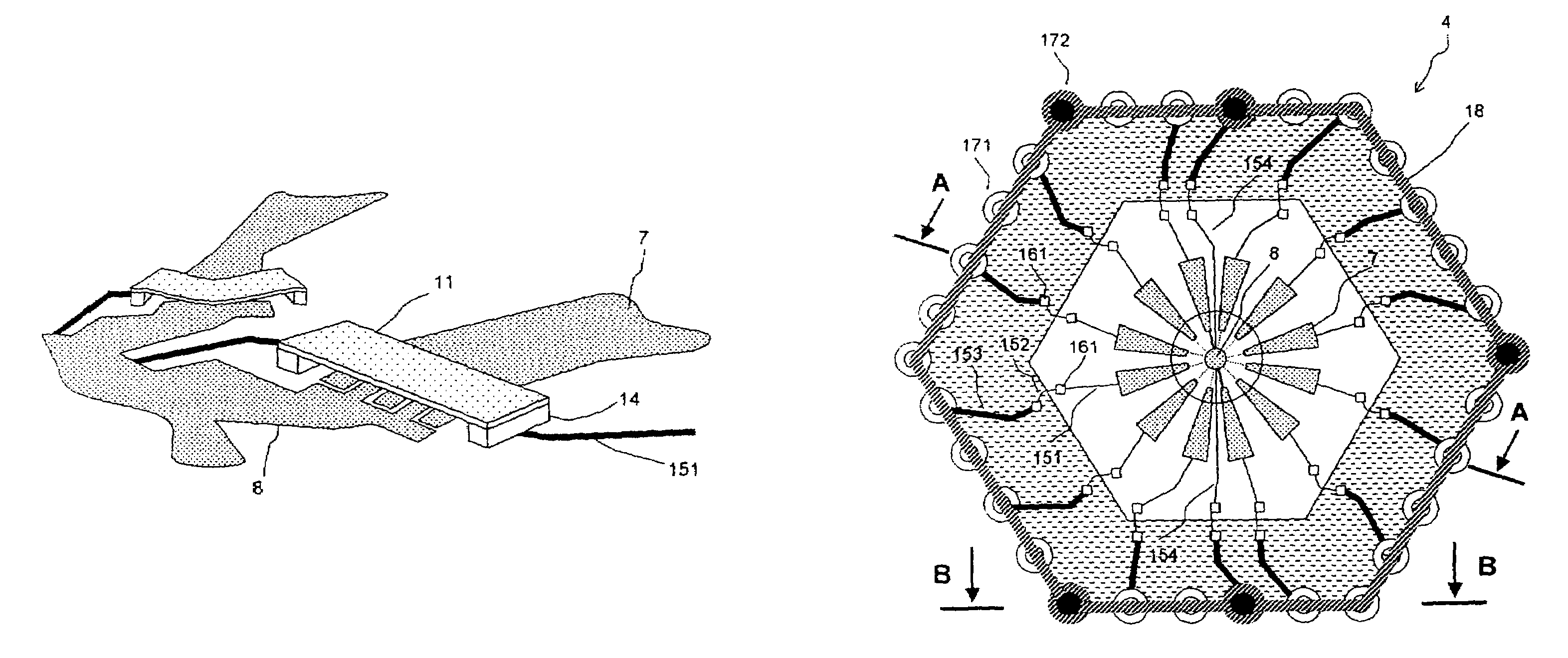
[0068]FIG. 7 shows a top view of the switching devices according to the invention. Two adjacent conducting strands 7 of a phase-shifting cell 4 are shown, together with that part of the central disk 8 facing them. The switching region of each strand is formed by the end of the strand located opposite the central disk. The switching device essentially comprises a membrane 11 placed above the switching region. The control voltages and groundings are applied by means of resistive lines 151, 154 and 155.

[0069]FIG. 8 shows a detailed view of the switching region. That end 71 of each strand placed on the side facing the central disk and that corresponding part 81 of the disk placed facing this end make up a comb of interdigitated fingers. The region of this comb constitutes the switching region. The advantage of this geometrical arrangement is that it allows the control voltage coming from the strand to be distributed uniformly in the switching region. As an example, FIG. 8 shows five int...


PUM


Abstract

The invention relates to phase-shifting cells constituting the passive reflectarrays of antennas with a reconfigurable transmission direction, transmitting in the microwave range. More particularly, the invention describes, within the context of phase-shifting cells of the type having dipole strands angularly distributed in a star configuration, a novel type of switch consisting of a microelectromechanical device essentially comprising a suspended micromembrane which, under the action of an electrostatic force caused by a control voltage, deforms sufficiently to ensure electrical connection between the strands, making it possible to form a dipole in the desired orientation. In one particular embodiment, the micromembrane can be likened to one of the plates of a capacitor and its deformation corresponds to a substantial increase in the capacitance of this capacitor, thus providing the electrical connection. This switch technology has the advantages of greater fabrication simplicity and of enhanced performance compared with the known technologies. The invention provides the main geometrical and technological characteristics for obtaining optimized performance.

Description

CROSS-REFERENCE TO RELATED APPLICATIONS[0001]The present Application is based on International Application No. PCT / FR03 / 01803, filed on Jun. 13, 2003, which in turn corresponds to FR 02 / 07743 filed on Jun. 21, 2002, and priority is hereby claimed under 35 USC §119 based on these applications. Each of these applications are hereby incorporated by reference in their entirety into the present application.FIELD OF THE INVENTION[0002]The field of the invention is that of passive reflectarrays composed of a mosaic of elementary phase-shifting cells for an antenna with a reconfigurable transmission direction, operating in the microwave range.[0003]In a large number of applications, it is necessary to be able to point the electromagnetic beam transmitted by an antenna in the desired direction. The possible applications are in particular:[0004]space telecommunications: tracking of an area on the ground in the case of an orbiting satellite, minimization of the interfering radiation when there...

Claims


Application Information

Patent Timeline
IPC IPC(8): H01Q1/38H01Q13/00H01Q3/46H01Q9/06H01Q21/06
CPCH01Q3/46H01Q21/062H01Q9/065
Inventor CHARRIER, MICHELDEAN, THIERRYZIAEI, AFSHINLEGAY, HERVEPINTE, BEATRICEGILLARD, RAPHAELGIRARD, ETIENNEMOULINET, RONAN
Owner THALES SA
Why Eureka
Try Eureka